104 External control unit
Connecting cables between the drive module and the control unit
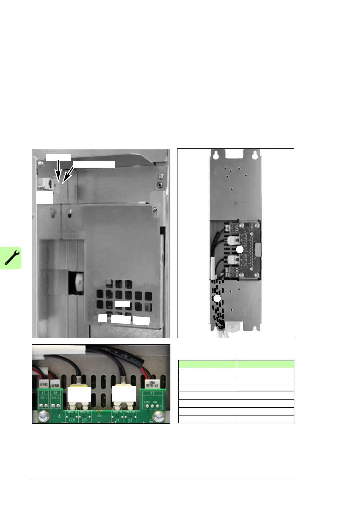
In the drive module:
1. Connect power supply cable to terminal X2.
2. Connect the STO cable to the INU STO connector.
3. Connect the fiber optic cables to the QOIA V8, V13, V2 and V7 connectors.
In the control unit:
1. Pull the fiber optic, power supply and STO cables through the hollow back frame of the
control unit.
2. Connect the cables to the ZBIB terminals..
QOIA ZBIB
X7 (STO1) X7 (STO1)
X8 STO2) X8 (STO2)
X2 X3
V2 V2
V7 V1
V8 V21
V13 V22
INU ZBIB
V1 V2
ISU ZBIB
V20 V21
2
1
V
8
V
1
3
ISU
panel
QOIA
V
2
V
7
INU STO
X
2
ISU ext. 24VDC

 Loading...


