Resistor braking 231
EMC compliance of the complete installation
Note: ABB has not verified that the EMC requirements are fulfilled with external custom
brake resistors and cabling. The customer must consider the EMC compliance of the
complete installation.
Placing the brake resistors
Install the brake resistors outside the drive module in a place where they will cool.
Arrange the cooling of the resistor in a way that:
• no danger of overheating is caused to the resistor or nearby materials
• the temperature of the room the resistor is located in does not exceed the allowed
maximum.
Supply the resistor with cooling air or coolant according to the resistor manufacturer’s
instructions.
WARNING! The materials near the brake resistor must be non-flammable. The
surface temperature of the resistor is high. Air flowing from the resistor is of
hundreds of degrees Celsius. If the exhaust vents are connected to a ventilation
system, make sure that the material withstands high temperatures. Protect the resistor
against contact.
Protecting the system against thermal overload
The brake chopper protects itself and the resistor cables against thermal overload when
the cables are dimensioned according to the nominal current of the drive. The drive control
program includes a resistor and resistor cable thermal protection function which can be
tuned by the user. See the firmware manual.
ABB requires:
• main contactor for protecting against resistor overheating
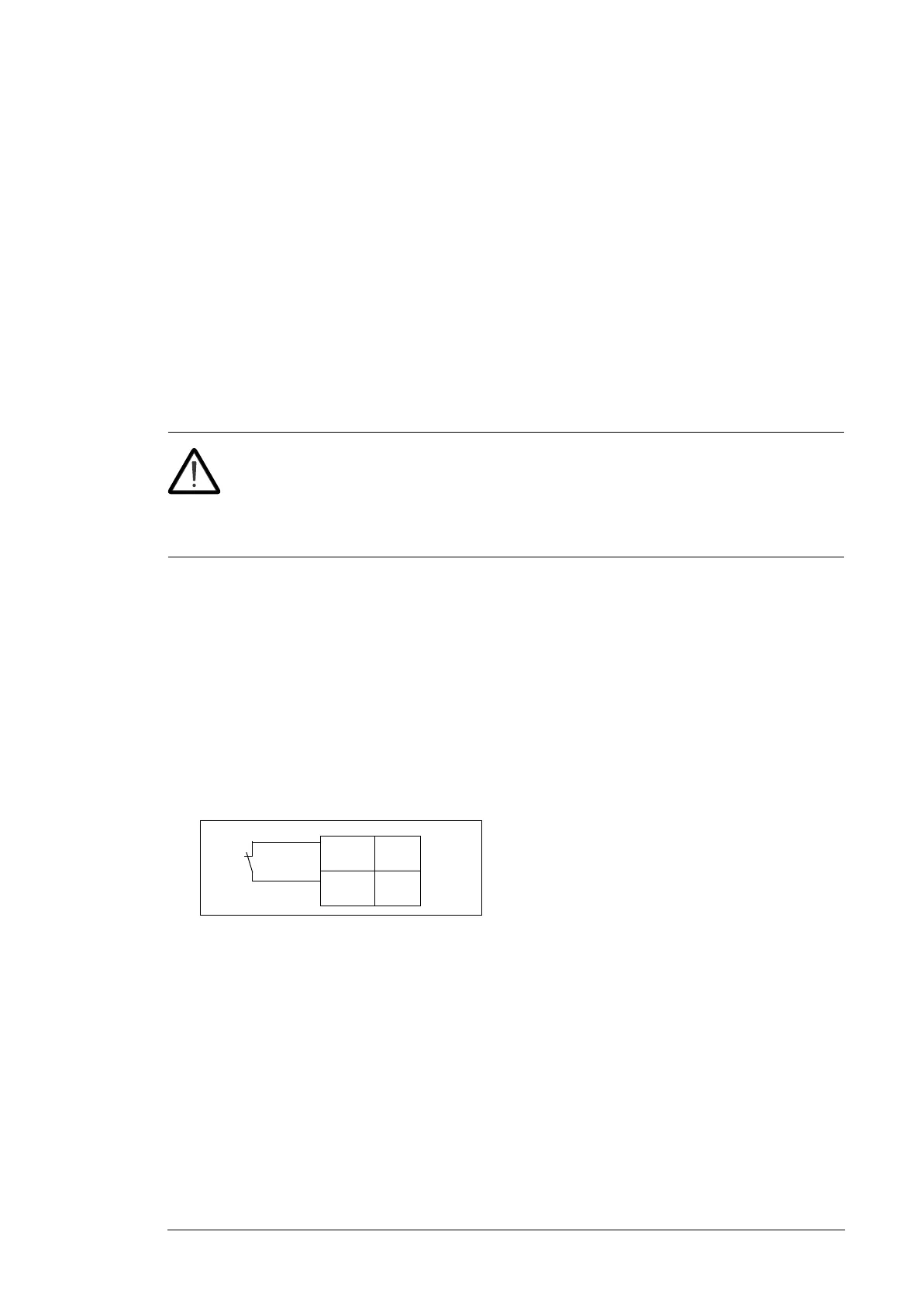
• thermal switch (standard in ABB resistors) for safety reasons. The thermal switch
cable must be shielded and may not be longer than the resistor cable. Wire the switch
to a digital input on the drive control unit as shown in the figure below.
Protecting the resistor cable against short-circuits
The DC fuses for the brake chopper protection protect the resistor cable against short-
circuits.
Mechanical installation of brake resistors
All brake resistors must be installed outside the drive. Obey the resistor manufacturer’s
instructions.

 Loading...


