134 Installation example of the standard drive module configuration
constant pressure with one foot on the base of the module to prevent the module from
falling on its back
• Unfasten the insertion ramp and attach the LCL filter module to bottom plate.
• Attach the drive module pedestal guide plate to the cabinet bottom plate.
• Attach the telescopic insertion ramp to the pedestal guide plate.
• Remove the sheeting from the clear plastic shrouds of the drive module from both
sides.
• Install the top metallic shroud to the drive module.
• Install the back shrouds to the drive module.
• To prevent the drive module from falling, attach its lifting lugs with chains to the cabinet
frame.
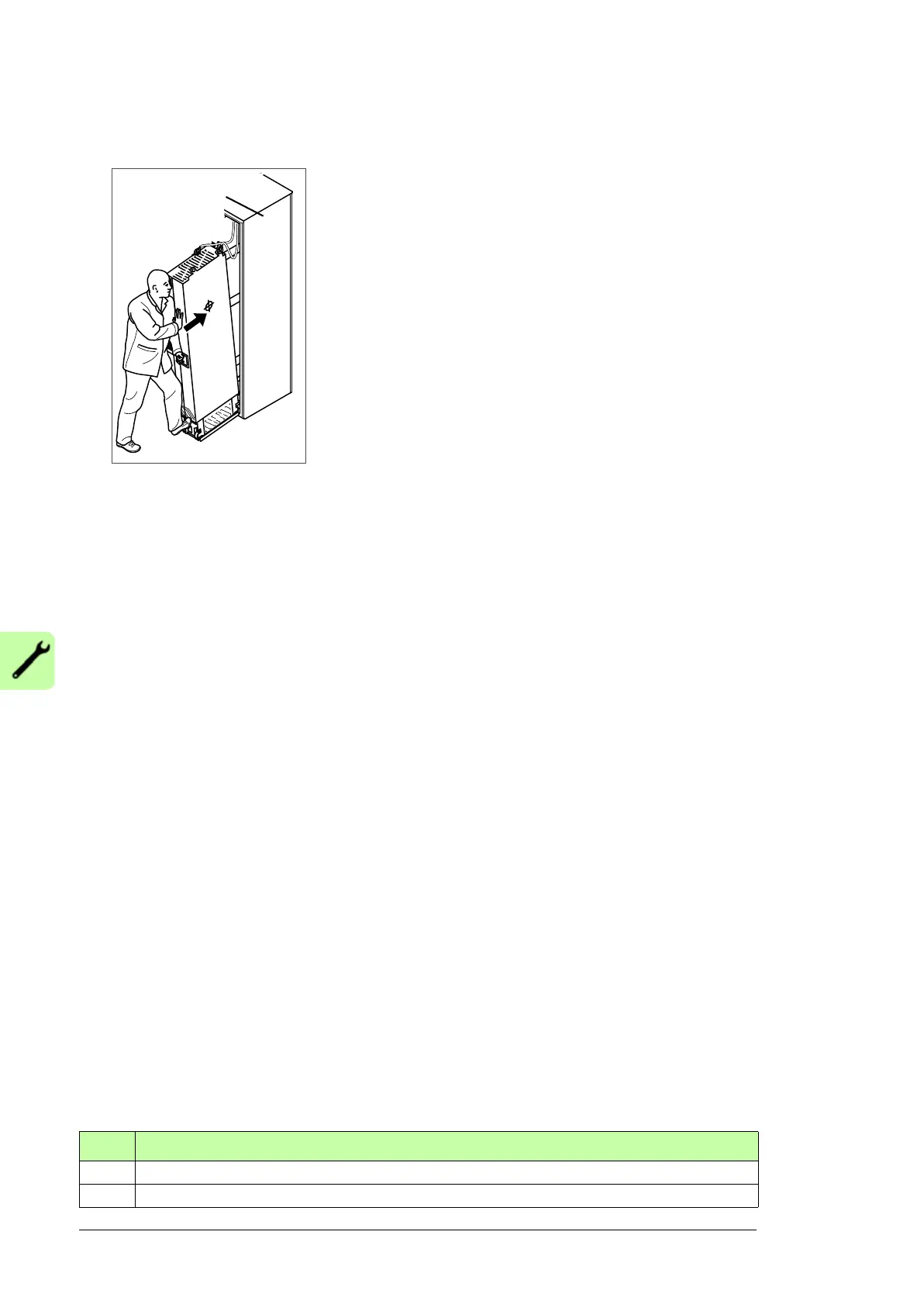
• Push the driver module carefully into the cabinet along the telescopic insertion ramp.
Work preferably with help from another person as shown above. Keep a constant
pressure with one foot on the base of the module to prevent the module from falling on
its back.
• Unfasten the insertion ramp and attach the drive module to the bottom plate.
• Attach the LCL filter module and drive module to the punched section.
• Attach LCL filter module to the side of drive module from top and bottom. Reinstall the
cover.
• Connect the LCL filter busbars to the drive module busbars with the connecting
busbars.
• Connect the LCL filter fan power supply cable to connector FAN3:LCL.
• Connect the power cables and install the shrouds as described in section Connecting
the power cables and installing the shrouds on page 134.
• Install the external control unit and connect the control cables as described in chapter
Installation instructions on page 77.
• Install the air baffles.
Connecting the power cables and installing the shrouds
Step Task (motor cables)
1 Install the grounding terminal to the drive module base.
2 Run the motor cables to the cabinet. Ground the cable shields 360 degrees at the cabinet entry
 Loading...


