Internal control unit (option +P905) 121
Connecting the control cables to the internal control unit (option
+P905)
1. Ground the outer control cable shields 360 degrees at the cabinet entry plate
(recommendation).
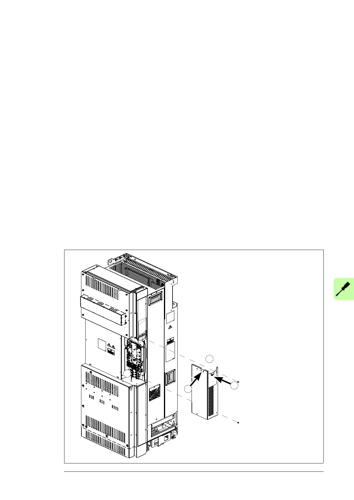
2. Remove the middle front cover of the drive module (view of standard drive module
configuration below).
3. Fasten the clamp plate to the bottom of the control unit with two screws from front, see
Attaching the control cable clamp plate on page 102.
4. Fasten the optional modules if not fastened already.
5. Remove the cover plate from the control cable entry and put the rubber grommet in its
place. Put the control cables through the grommet.
Note: If you route the control cables from top or bottom instead of front or side, you
need tho make holes for the entries to the clear plastic shrouds.
6. Ground the control cables at the clamp plate as described in Step 2 in section
Connecting the control cables to the terminals of the control unit on page 107.
7. Connect the conductors to the appropriate detachable terminals of the control unit
(see page 123). Use shrink tubing or insulating tape to contain any stray strands.
Tighten the screws to secure the connection.
Note: Keep any signal wire pairs twisted as close to the terminals as possible.
Twisting the wire with its return wire reduces disturbances caused by inductive
coupling.
8. Install the middle front cover back.
Combi screw
M4×8 Torx T20
2N·m
2
5
5
3

 Loading...


