30 Operation principle and hardware description
Block diagram of the main circuit of the drive module
Line-side converter
The line-side converter rectifies three-phase AC current to direct current for the
intermediate DC link of the drive.
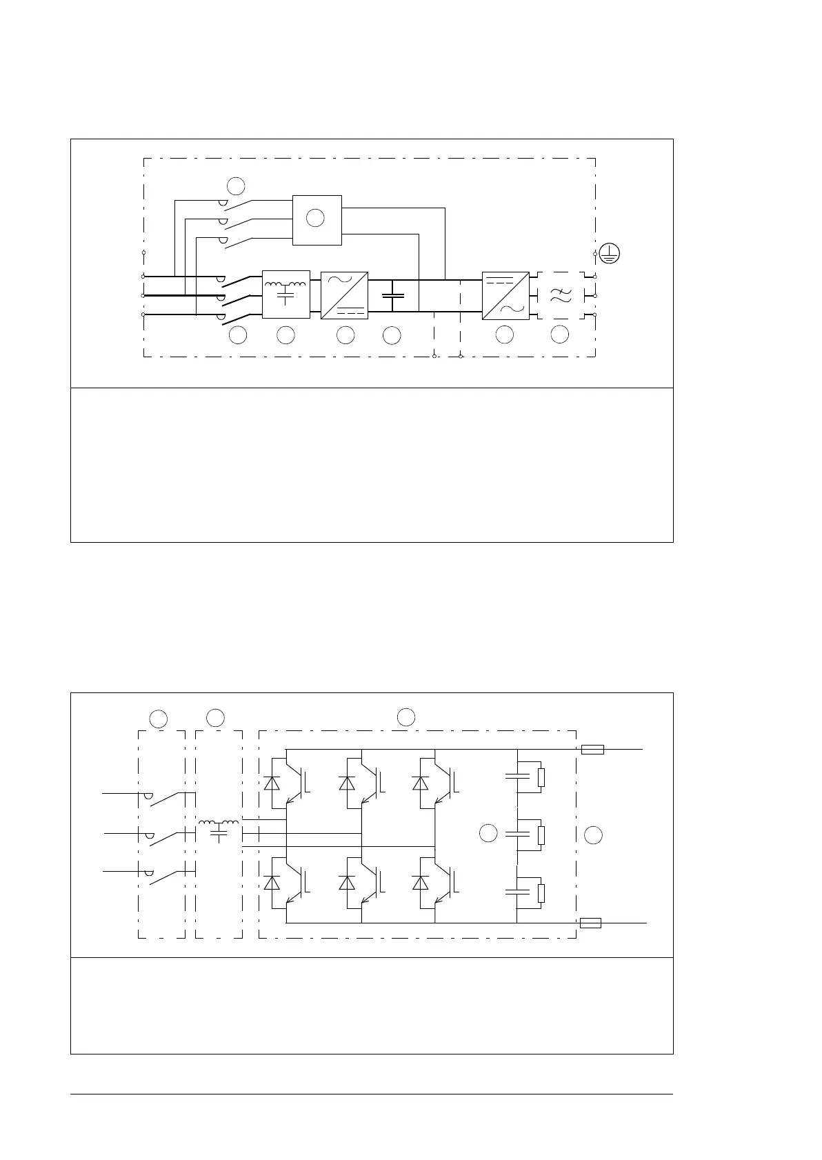
The following figure shows the simplified main circuit diagram of the line-side converter
part. The line-side converter is controlled by a type ZCU control unit located inside the
drive module.
1 Charging circuit contactor
2 Charging circuit
3 Line contactor
4 LCL filter
5 Line-side converter.
6 DC link. DC circuit between the line-side converter and motor-side converter
7 Motor-side converter.
8 Common mode filter (option +E208)
1 LCL filter contactor
2 LCL filter
3 Line-side converter
4 DC capacitors
5DC link
T1/U2
T2/V2
T3/W2
7
3
54
6
L1/U1
L2/V1
L3/W1
UDC- UDC+
PE
1
2
8
ACS880-34

 Loading...


