Guidelines for planning the cabinet installation 47
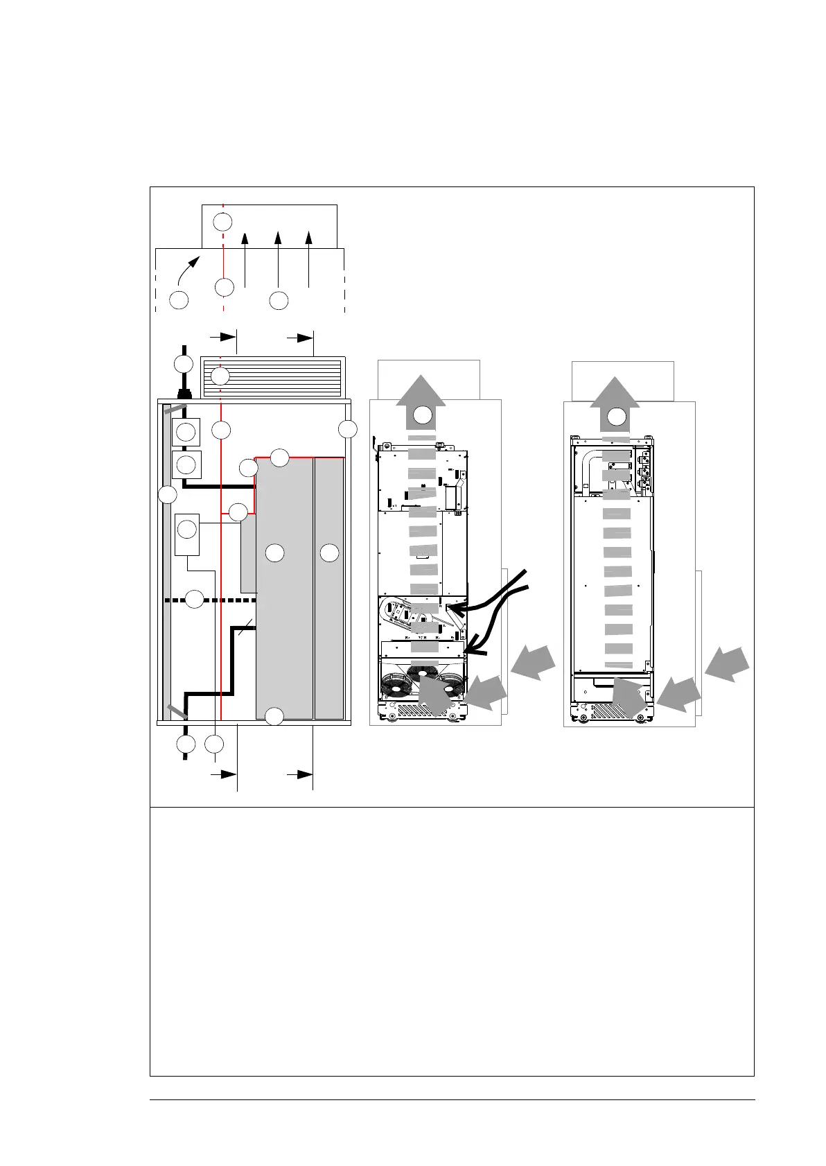
Layout example, door open (option +0B051)
This diagram shows a layout example for drive modules with no IP20 shrouds (option
+0B051) or no cabling panels (option +H381 not included).
1 Supporting frame of the cabinet 9 Motor cable including the protective ground conductor
of the drive module
2 Vertical (2a, 2b) and horizontal (2c, 2d) air
baffles that separate the cool and hot areas
(leak-proof lead-throughs). See also page
52.
10 Drive module control unit. Note: With an internal control
unit (option +P905), the upper door air inlet is critical for
proper cooling of the control board.
2e Optional air baffle that is needed when there
is no fan on the lower part of the cabinet
door (see 1b on page on 44)
11 External control cables
3 Cabinet grounding busbar (PE) 12 Grounding screws
4 Input power cable including the protective
ground conductor (PE) of the drive
13 Alternative to grounding screws (11)
5 Disconnector and fuses 14 Air flow to the roof
6 Contactor 15 Air flow through the drive module
7 Drive module 16 Air flow to the LCL filter module
8 LCL filter module - -
PE
T3/W2
T2/V2
T1/U2
1
4
5
6
7
9
3
2a
2a
13
14
10
11
3
2d
2e
2e
L1/U1
L2/V1
L3/W1
2b
2c
14
12
A
A
A – A
15
B– B
16
B
B
8

 Loading...


