62 Guidelines for planning the electrical installation
Additional data for calculating the rise time and the peak line-to-line voltage
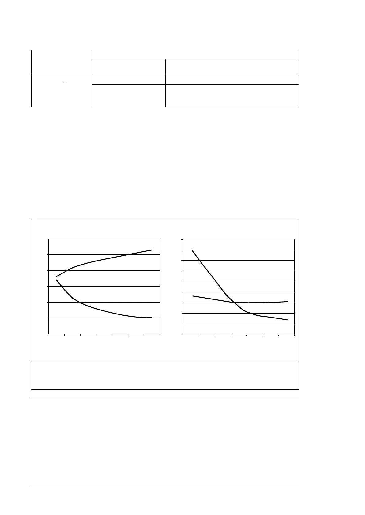
The diagrams below show the relative peak line-to-line voltage and rate of change of
voltage as a function of the motor cable length with and without a du/dt filter in use.
To calculate the actual peak voltage for a certain cable length read the relative Û
LL
/U
N
value from the appropriate diagram and multiply it by the nominal supply voltage (U
N
).
To calculate the actual voltage rise time for a certain cable length read the relative values
Û
LL
/U
N
and (du/dt)/U
N
from the appropriate diagram. Multiply the values by the nominal
supply voltage (U
N
) and substitute into equation t = 0.8 · Û
LL
/(du/dt).
Additional note for sine filters
Sine filters protect the motor insulation system. Therefore, the du/dt filter can be replaced
with a sine filter. The peak phase-to-phase voltage with the sine filter is approximately
1.5 · U
N
.
Additional note for common mode filters
Common mode filters are available as plus code option +E208.
600 V < U
N
< 690 V Reinforced: Û
LL
= 1800 V + N + du/dt + CMF
Reinforced: Û
LL
= 2000 V,
0.3 microsecond rise time
***
N + CMF
***If the intermediate DC circuit voltage of the drive is increased from the nominal level by resistor braking,
check with the motor manufacturer if additional output filters are needed in the applied drive operation
range.
Drive with du/dt filter Drive without du/dt filter
I Motor cable length
Û
LL
/U
N
Relative peak line-to-line voltage
du/dt /U
N
Relative du/dt value
Note: ÛLL and du/dt values are approximately 20% higher with resistor braking.
Nominal AC supply
voltage
Requirement for
Motor insulation system ABB du/dt filter, insulated N-end bearing and ABB
common mode filter
100 200 300
0.0
0.5
1.0
1.5
2.0
2.5
3.0
l (m)
du/dt
U
N
-------------(1/s)
Û
LL
/U
N
Û
LL
/U
N
l (m)
du/dt
U
N
-------------(1/s)
1.0
2.0
5.0
4.0
3.0
1.5
2.5
3.5
4.5
100 200 300
5.5

 Loading...


