Internal control unit (option +P905) 125
See the firmware manual of the drive for the related parameter settings.
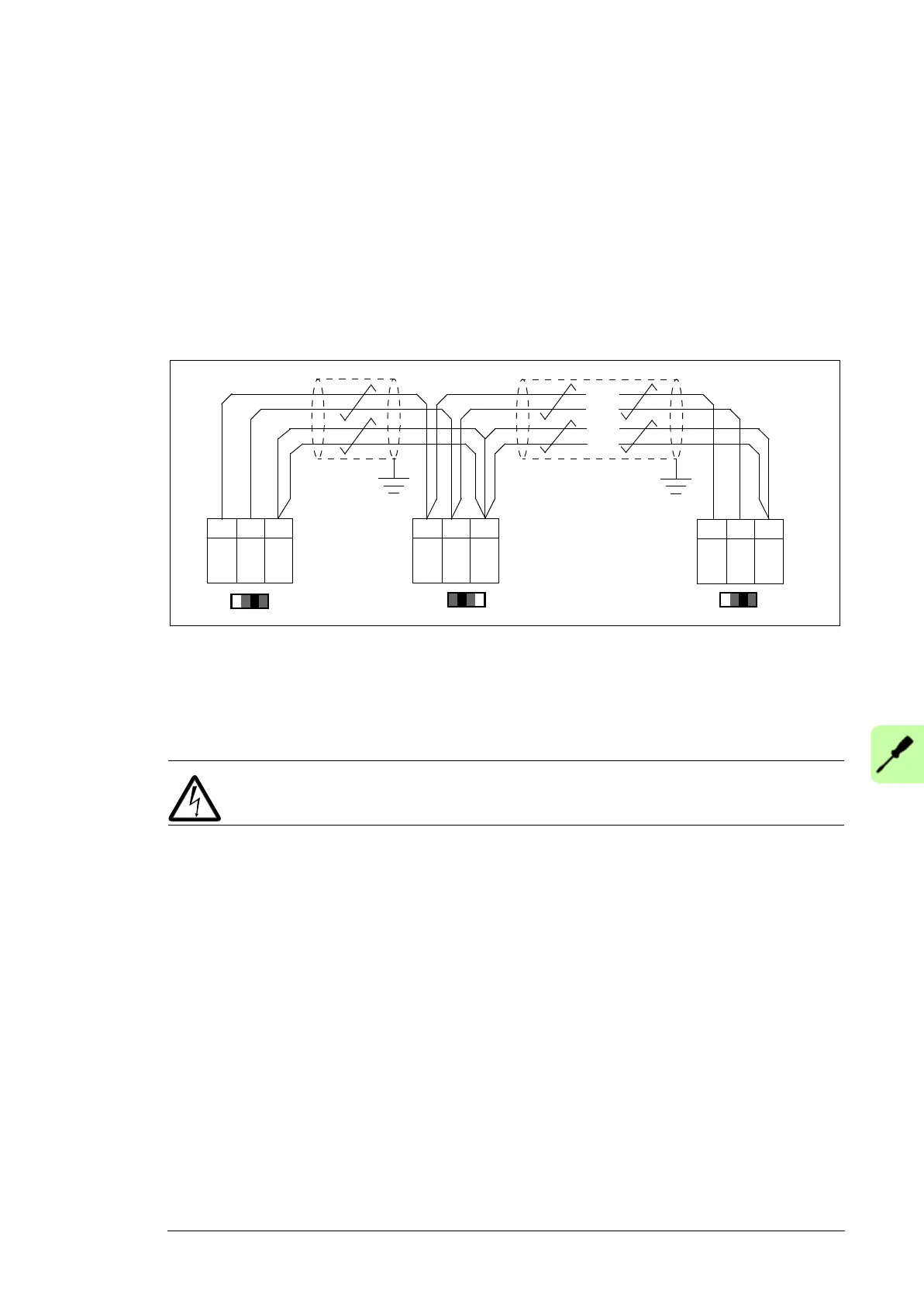
Set termination activation jumper J3 (see section Jumpers and switches above) next to
this terminal block to the ON position on the drives at the ends of the drive-to-drive link. On
intermediate drives, set the jumper to the OFF position.
Use shielded twisted-pair cable with a twisted pair for data and a wire or another pair for
signal ground (nominal impedance 100 to 165 ohm, for example Belden 9842) for the
wiring. For best immunity, ABB recommends high quality cable. Keep the cable as short as
possible. Avoid unnecessary loops and running the cable near power cables (such as
motor cables).
This diagram shows the wiring of the drive-to-drive link.
Installing optional modules
Installing the FSO safety functions module (option +Q973)
Install the FSO safety functions module in Slot 2 of the control unit as described below.
WARNING! Obey the safety instructions in chapter Safety instructions. If you
ignore them, injury or death, or damage to the equipment can occur.
1. Stop the drive and do the steps in section Precautions before electrical work on page
18 before you start work.
2. If the bottom plate of the FSO-xx module looks different from that in the drawing below,
remove the bottom plate and attach the alternative bottom plate from the FSO
package to module.
3. Connect the FSO-xx data cable to connector X12 on the control unit.
4. Attach the FSO-xx module to Slot 2 with four screws.
5. Tighten the FSO module electronics grounding screw to 0.8 N·m. Note: The screw
tightens the connections and grounds the module. It is essential for fulfilling the EMC
requirements and for proper operation of the module.
6. Connect the FSO-xx data cable to FSO-xx connector X110.
7. Connect the Safe torque off four-wire cable to connector X111 on the module and to
connector XSTO on the drive module control unit.
J3
XD2D
XD2D
J3
XD2D
A
BGND
B
1
2
3
A
BGND
B
1
2
3
A
BGND
B
1
2
3
. . .
. . .
. . .
. . .
J3

 Loading...


