Operation principle and hardware description 35
Power module with full power cabling panels (option +H381)
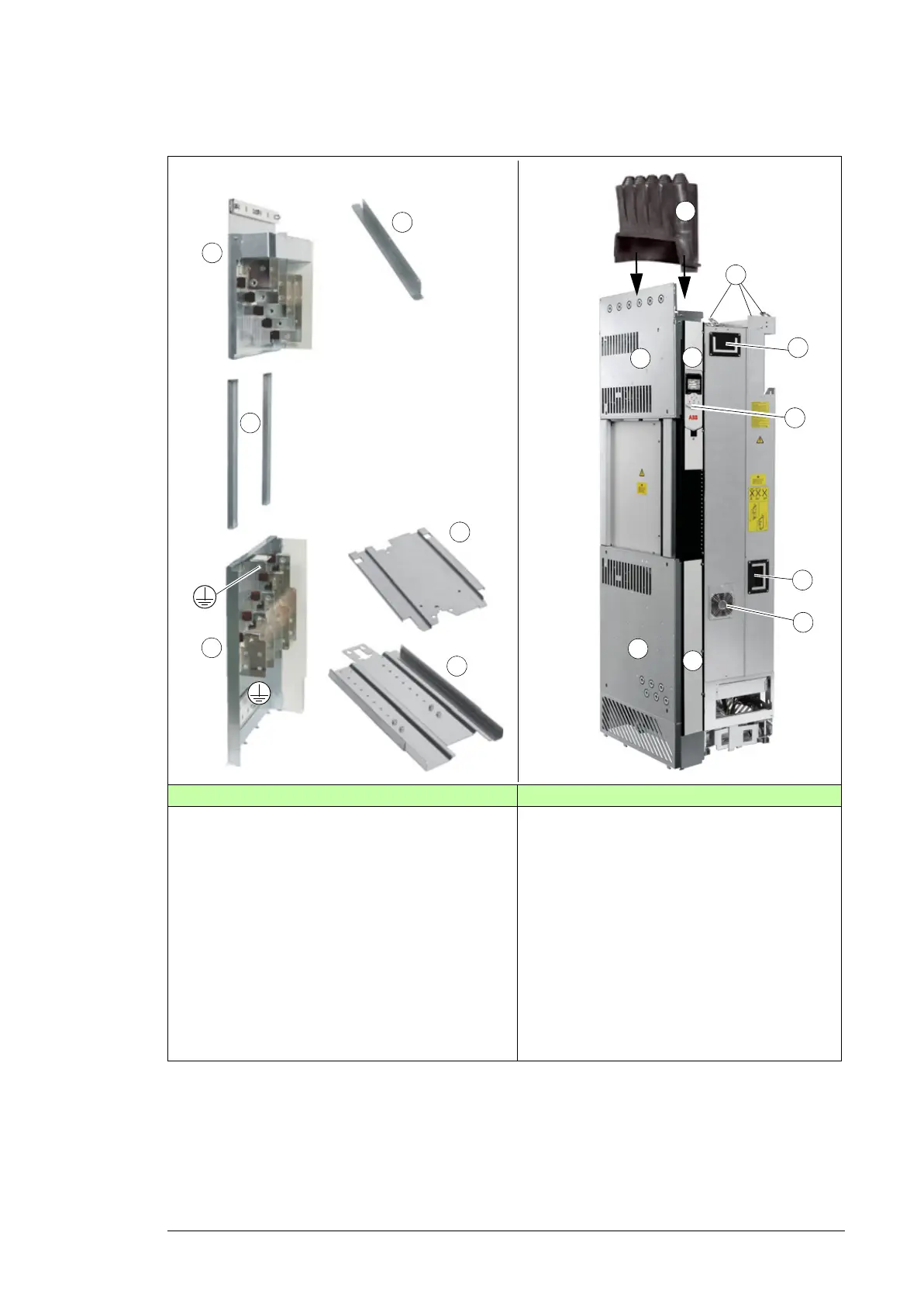
Accessories Assembled power module
1 Input power cabling panel 8 Input power cabling panel to be attached to
the drive cabinet
2 Side guides 9 Output power cabling panel to be attached
to the drive cabinet
3 Output power cabling panel 10 Front cover
4 Top guide plate 11 Internal control unit (option +P905) and
control panel holder mounted on the drive
module (option +J414)
5 Pedestal guide plate 12 Handle
6 Telescopic extraction and insertion ramp 13 Lifting lugs
7 Rubber grommet 14 Auxiliary cooling fan, another auxiliary
cooling fan is located below the circuit
board compartment, see page 162.

 Loading...


