Operation principle and hardware description 33
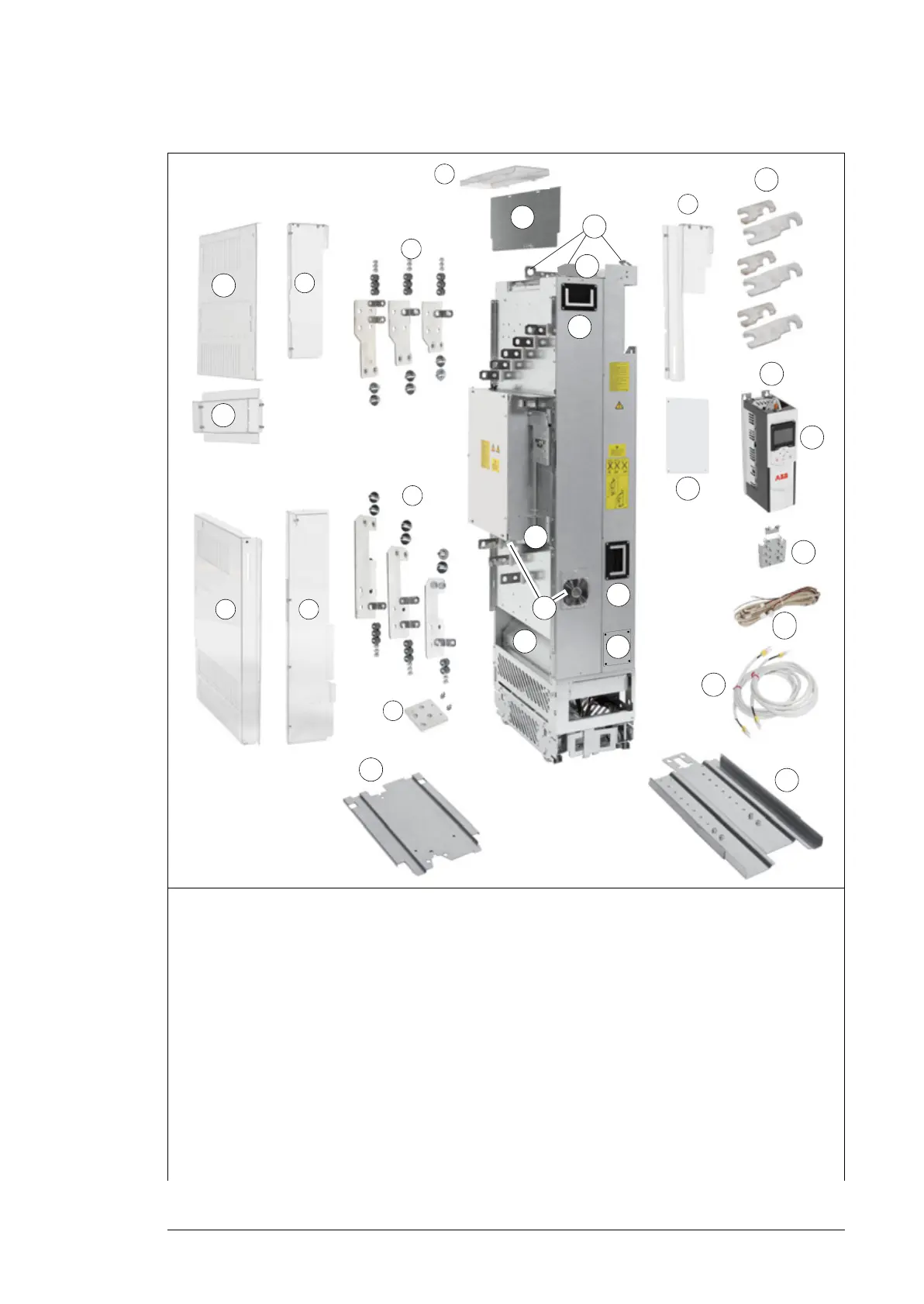
Converter module
1 Clear plastic shroud to be attached onto the
drive module input power cabling (a). entry
shroud for side cabling (b).
14 Pedestal guide plate for the drive module
2 Clear plastic shrouds to be attached onto the
drive module output power cabling
15 Telescopic extraction and insertion ramp
3 Clear plastic shroud to be attached on top of
the drive module (entry for top cabling)
16 External control unit. The control unit can also
be inside the drive module (option +P905)
4 Upper back clear plastic shroud 17 Control panel
5 Lower back clear plastic shroud 18 Control cable clamp plate
6 Front clear plastic shroud 19 Cables for connecting the control unit to the
drive module (ZBIB - INU STO and 24VDC
power)
7 Input power cable connection terminals
(option +H370)
20 Busbars for connecting the drive module to
the LCL filter electrically
8 Output power cable connection terminals 21 Cover for the busbar connection
6
3
+H370
2
4
5
8
11
10
12
13
14
16
17
18
19
1a
1b
7
9
20
21
15
23
23
22
25
24
26

 Loading...


