Guidelines for planning the electrical installation 63
Selecting the power cables
General rules
Select the input power and motor cables according to local regulations:
• Select a cable capable of carrying the drive nominal current. See section Ratings
(page 183) for the rated currents.
• Select a cable rated for at least 70 °C (158 °F) maximum permissible temperature of
conductor in continuous use. For US, see Additional US requirements, page 66.
• The inductance and impedance of the PE conductor/cable (grounding wire) must be
rated according to permissible touch voltage appearing under fault conditions (so that
the fault point voltage will not rise excessively when a ground fault occurs).
• 600 V AC cable is accepted for up to 500 V AC. 750 V AC cable is accepted for up to
600 V AC. For 690 V AC rated equipment, the rated voltage between the conductors
of the cable should be at least 1 kV.
Use symmetrical shielded motor cables (see page 66). Ground motor cable shields 360° at
both ends. Keep the motor cable and its PE pigtail (twisted shield) as short as possible to
reduce high-frequency electromagnetic emissions.
Note: When continuous metal conduit is employed, shielded cable is not required. The
conduit must have bonding at both ends.
A four-conductor system is allowed for input cabling, but shielded symmetrical cable is
recommended.
Compared to a four-conductor system, the use of symmetrical shielded cable reduces
electromagnetic emission of the whole drive system as well as the stress on motor
insulation, bearing currents and wear.
The protective conductor must always have an adequate conductivity.
Unless local wiring regulations state otherwise, the cross-sectional area of the protective
conductor must agree with the conditions that require automatic disconnection of the
supply required in 411.3.2. of IEC 60364-4-41:2005 and be capable of withstanding the
prospective fault current during the disconnection time of the protective device.
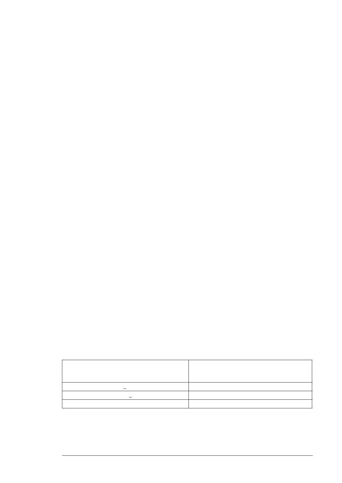
The cross-sectional area of the protective conductor can either be selected from the table
below or calculated according to 543.1 of IEC 60364-5-54.
This table shows the minimum cross-sectional area related to the phase conductor size
according to IEC 61800-5-1 when the phase conductor and the protective conductor are
made of the same metal. If this is not so, the cross-sectional area of the protective earthing
conductor shall be determined in a manner which produces a conductance equivalent to
that which results from the application of this table.
Cross-sectional area of the phase conductors
S (mm
2
)
Minimum cross-sectional area of the
corresponding protective conductor
S
p
(mm
2
)
S <
16 S
16 < S <
35 16
35 < S S/2

 Loading...


