24 Introduction to the manual
from the option codes visible on the type designation label. The option selections are listed
in section Type designation key on page 39.
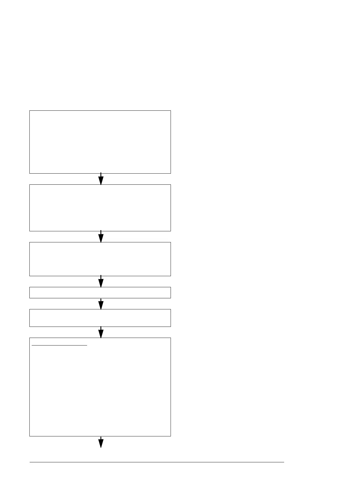
Quick installation, commissioning and operating
flowchart
Task See
Plan the mechanical and electrical installation and acquire
the accessories needed (cables, fuses, etc.).
Check the ambient conditions, ratings, required cooling air
flow, input power connection, compatibility of the motor,
motor connection, and other technical data.
Guidelines for planning the cabinet installation
(page 43)
Guidelines for planning the electrical installation
(page 57)
Technical data (page 183)
Resistor braking (page 229)
Option manual (if optional equipment is
included)
Unpack and check the units.
Check that all necessary optional modules and equipment
are present and correct.
Only intact units can be started up.
Moving and unpacking the unit (page 78)
Checking the delivery (page 85)
If the drive module has been non-operational
for more than three years, the converter DC link
capacitors need to be reformed. (Reforming the
capacitors, page 171)
Check the installation site. Fasten the base of the cabinet to
the floor.
Checking the installation site (page 77)
Ambient conditions (page 196)
Guidelines for planning the cabinet installation
(page 43)
Route the cables. Routing the cables (page 67)
Check the insulation of the supply cable, the motor and the
motor cable and the resistor cable (if present).
Checking the insulation of the assembly (page
85)
Standard dr
ive modules
• Install the additional components into the cabinet: for
example, main disconnector, main contactor, main AC
fuses, etc..
• Install the drive module into the cabinet.
• Connect the motor cables to the drive module terminals.
• Connect the DC connection cables (if any) to the drive
module terminals.
• If the main disconnector is installed into the cabinet,
connect it to the drive module terminals and the input
power cabling to the disconnector.
• Connect the cables from the drive module to the external
control unit and install the control unit into the cabinet.
Installing the drive module and LCL filter
module into a cabinet (page 133)
Connecting the power cables and installing the
shrouds (page 134)
Connecting the external control unit to the drive
module (page 103)
Mounting the external control unit (page 105)
Manuals for any optional equipment

 Loading...


