32 Operation principle and hardware description
Layout
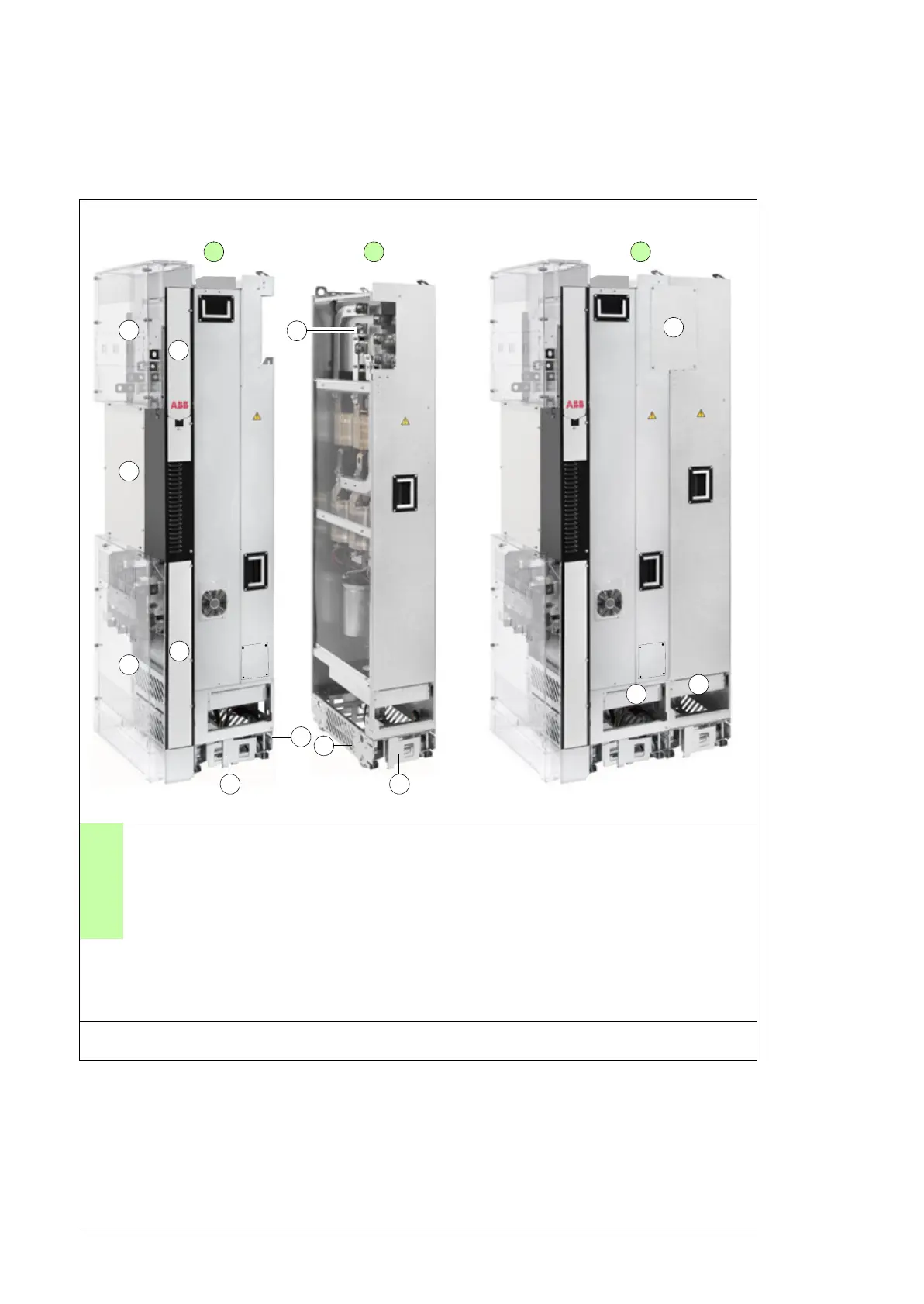
Standard drive module configuration
A Converter module. Contains line-side
converter and motor side converter. This can
also be called drive module.
4 Lower front cover
B LCL filter module 5 Cooling fan cassette
C LCL filter module connected to the converter
module
6 Support legs
1 Clear plastic shrouds attached 7 Pedestal
2 Circuit board compartment 8 Busbars for connecting the LCL filter module
to the converter module
3 Upper front cover 9 Cover on busbar connections
See the next page for descriptions and photos of the external control unit and converter module. For LCL
filter module, see page 34.

 Loading...


