Guidelines for planning the cabinet installation 53
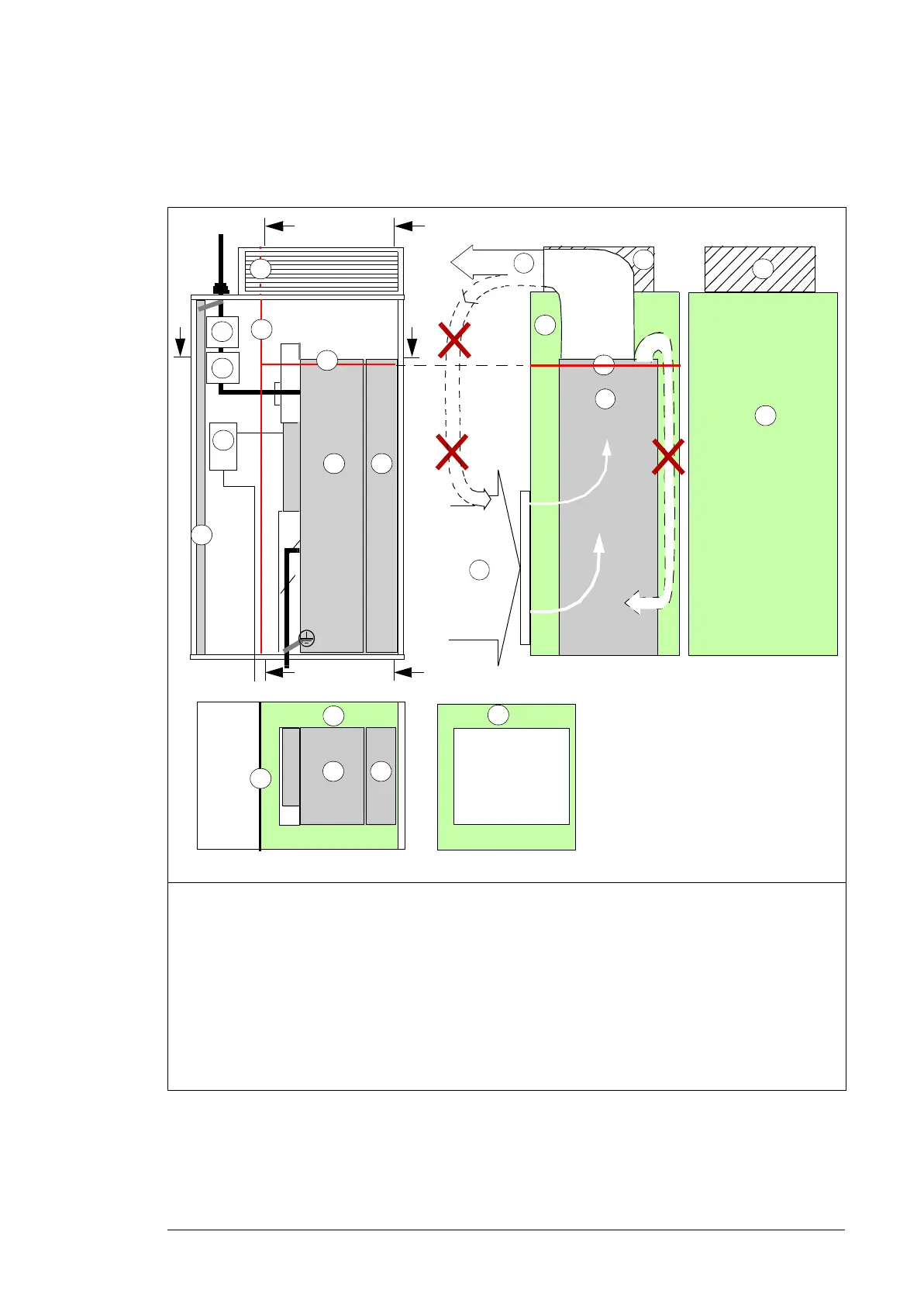
Bookshelf mounting (standard drive module configuration)
This diagram shows the air baffle position inside an example cabinet. For dimensions of
the baffle, see page 212.
1 Air flow to the drive modules, max. 40 °C
(104 °F)
5 Disconnector and fuses
2a Vertical air baffle that separates the cool and
hot areas in the cabinet
6 Contactor
2b Horizontal air baffle 7 Drive control unit
2c Optional air baffle that is needed when there is
no fan on the lower part of the cabinet door
(see 2 on page 44).
8 Air flow out
3 Drive module 9 Cabinet grounding busbar (PE)
4 LCL filter module - -
1
8
B – B
2a
2b
2a
2a
2c
3
2c
2b
A – A
C – C
2b
PE
T3/W2
T2/V2
T1/U2
5
6
3
9
2a
7
3
2c
L1/U1
L2/V1
L3/W1
2b
C
C
3
4
B
B
A
A
3 4
 Loading...


