86 Installation instructions
Motor and motor cable
Check the insulation of the motor and motor cable as follows:
1. Stop the drive and do the steps in section Precautions before electrical work on page
18 before you start the work.
2. Check that the motor cable is disconnected from the drive output terminals T1/U2,
T2/V2 and T3/W2.
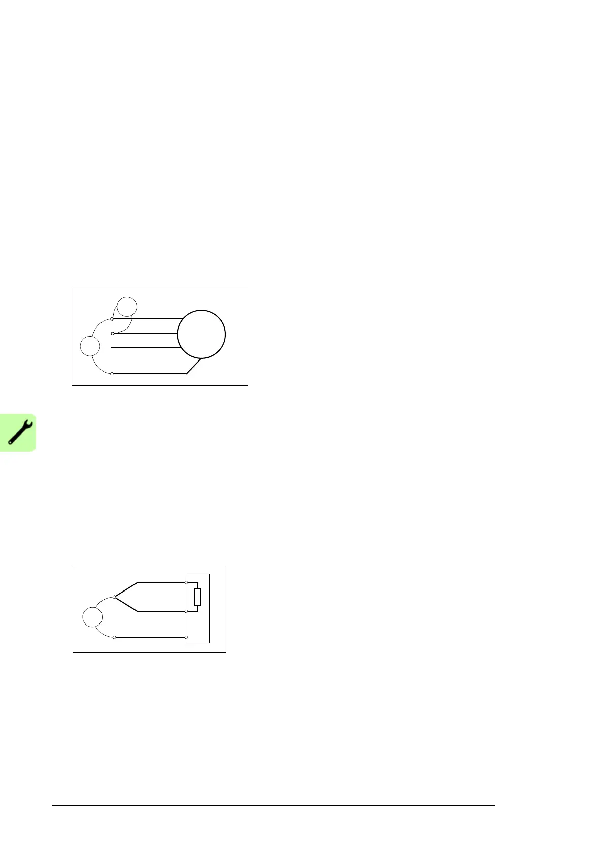
3. Measure the insulation resistance between each phase conductor and then between
each phase conductor and the Protective Earth conductor using a measuring voltage
of 1000 V DC. The insulation resistance of an ABB motor must exceed 100 Mohm
(reference value at 25 °C or 77 °F). For the insulation resistance of other motors,
consult the manufacturer’s instructions. Note: Moisture inside the motor casing will
reduce the insulation resistance. If you suspect moisture, dry the motor and repeat the
measurement.
Brake resistor and resistor cable
Check the insulation of the brake resistor assembly (if present) as follows:
1. Stop the drive and do the steps in section Precautions before electrical work on page
18 before you start the work.
2. Check that the resistor cable is connected to the resistor, and disconnected from the
brake chopper output terminals.
3. At the brake chopper end, connect the R+ and R- conductors of the resistor cable
together. Measure the insulation resistance between the conductors and the PE
conductor by using a measuring voltage of 1 kV DC. The insulation resistance must be
higher than 1 Mohm.

 Loading...


