194 Technical data
Network type TN (grounded) and IT (ungrounded) systems
Short-circuit withstand
strength (IEC 61439-1)
Maximum allowable prospective short-circuit current is 65 kA when by the
fuses given in the fuse table. For the maximum allowable prospective short-
circuit current with circuit breakers, see section Protecting the drive and input
power cable in short-circuits on page 69.
Short-circuit current protection
(UL 61800-5-1)
The drive is suitable for use on a circuit capable of delivering not more than
100,000 rms symmetrical amperes at 600 V maximum when protected by
fuses given in the fuse table.
Short-circuit current protection
(CSA C22.2 No. 14-05)
The drive is suitable for use on a circuit capable of delivering not more than
100 kA rms symmetrical amperes at 600 V maximum when by the fuses
given in the fuse table.
Frequency (f
1
) 50/60 Hz, Variation ± 5% of nominal frequency.
Imbalance Max. ± 3% of nominal phase to phase input voltage
Power factor cos phi
1
= 1, cos phi (total) = 0.99
Harmonic distortion Harmonics are below the limits defined in IEEE519, IEC61000-3-12 and G5/4
standards.
The table below shows typical results on indicated networks. Values are
measured at the input terminals of the drive.
Motor connection data
Motor types Asynchronous AC induction motors, permanent magnet motors, AC induction
servomotors and ABB synchronous reluctance motors (SynRM motors)
Voltage (U
2
)0 to U
1
, 3-phase symmetrical. This is indicated in the type designation label
as typical output voltage level as 3 0…U
1
, U
max
at the field weakening
point.
Frequency (f
2
) 0…500 Hz
Note: Operation above 150 Hz can require type-specific derating. For more
information, contact your local ABB representative.
For drives with du/dt filter: 120 Hz
For drives with sine filter: 120 Hz
Frequency resolution 0.01 Hz
Current See section Ratings.
Frequency (f
2
) 0…500 Hz
For drives with du/dt filter:
Contact ABB
For drives with sine filter:
Contact ABB
Switching frequency 3 kHz (typically)
Maximum recommended
motor cable length
DTC control Scalar control
500 m (1640 ft) 500 m (1640 ft)
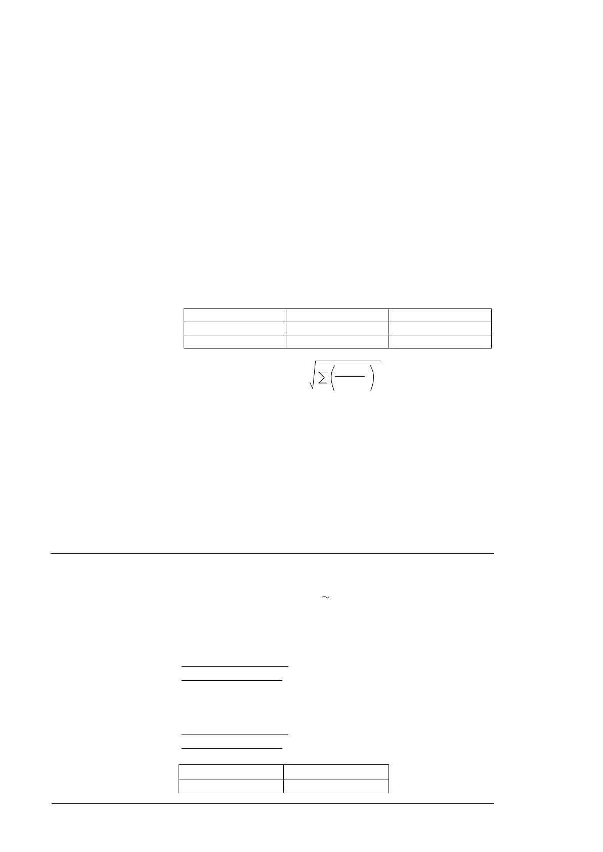
THD =
I
n
I
1contmax
50
2
2
R
sc
THD voltage (%) THD current (%)
20 3 2.5*
100 01.9 2.5*
THD Total harmonic distortion. The voltage THD depends on the short-
circuit ratio (Rsc). The spectrum of the distortion also contains
interharmonics.
I
n
nth harmonic component
R
sc
Short-circuit ratio. R
sce
= I
sc
/I
N
I
sc
Short-circuit current at point of common coupling (PCC)
I
1contmax
Continuous maximum input current of the line-side converter
I
L
Maximum demand load current

 Loading...


