128 Internal control unit (option +P905)
Technical data (ZCU-12)
Power supply
(XPOW)
Connector pitch 5 mm (0.2 in), wire size 2.5 mm
2
(14 AWG)
24 V (±10%) DC, 2 A
Supplied from the power unit of the drive, or from an external power supply
through connector XPOW. Connector pitch 5 mm (0.2 in), wire size 2.5 mm
2
(14 AWG).
Relay outputs RO1…RO3
(XRO1 … XRO3)
Connector pitch 5 mm (0.2 in), wire size 2.5 mm
2
(14 AWG)
250 V AC / 30 V DC, 2 A
Protected by varistors
+24 V output
(XD24:2 and XD24:4)
Connector pitch 5 mm (0.2 in), wire size 2.5 mm
2
(14 AWG)
Total load capacity of these outputs is 4.8 W (200 mA / 24 V) minus the
power taken by DIO1 and DIO2.
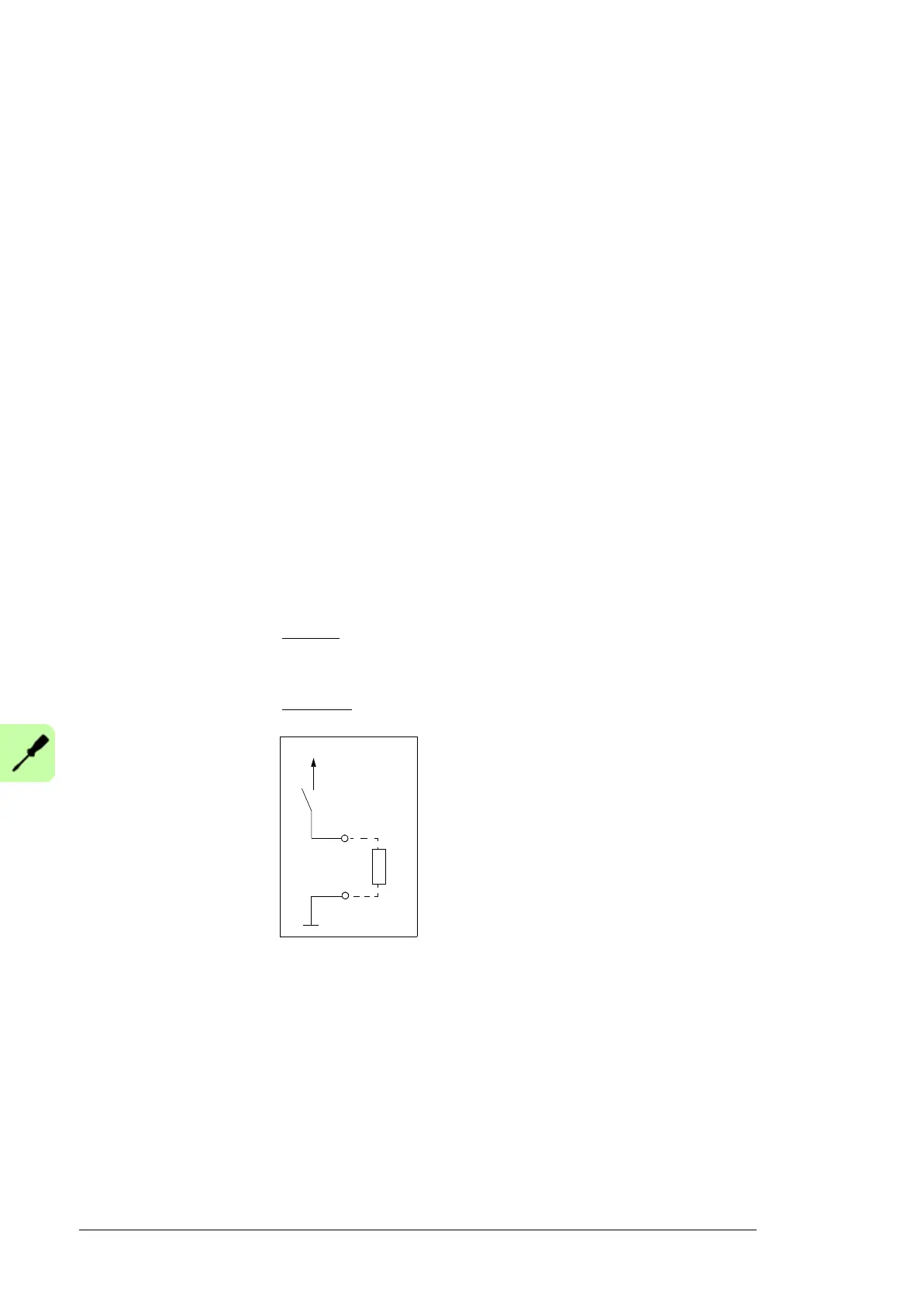
Digital inputs DI1…DI6
(XDI:1 … XDI:6)
Connector pitch 5 mm (0.2 in), wire size 2.5 mm
2
(14 AWG)
24 V logic levels: “0” < 5 V, “1” > 15 V
R
in
: 2.0 kohm
Input type: NPN/PNP (DI1…DI5), NPN (DI6)
Hardware filtering: 0.04 ms, digital filtering up to 8 ms
DI6 (XDI:6) can alternatively be used as an input for PTC sensors.
“0” > 4 kohm, “1” < 1.5 kohm
I
max
: 15 mA (for DI6 5 mA)
Start interlock input DIIL
(XD24:1)
Connector pitch 5 mm (0.2 in), wire size 2.5 mm
2
(14 AWG)
24 V logic levels: “0” < 5 V, “1” > 15 V
R
in
: 2.0 kohm
Input type: NPN/PNP
Hardware filtering: 0.04 ms, digital filtering up to 8 ms
Digital inputs/outputs DIO1
and DIO2
(XDIO:1 and XDIO:2)
Input/output mode selection
by parameters.
DIO1 can be configured as a
frequency input (0…16 kHz
with hardware filtering of 4
microseconds) for 24 V level
square wave signal
(sinusoidal or other wave form
cannot be used). DIO2 can be
configured as a 24 V level
square wave frequency
output. See the firmware
manual, parameter group 11.
Connector pitch 5 mm (0.2 in), wire size 2.5 mm
2
(14 AWG)
A
s inputs:
24 V logic levels: “0” < 5 V, “1” > 15 V
R
in
: 2.0 kohm
Filtering: 0.25 ms
As outputs:
Total output current from +24VD is limited to 200 mA.
Reference voltage for
analog inputs +VREF and
-VREF
(XAI:1 and XAI:2)
Connector pitch 5 mm (0.2 in), wire size 2.5 mm
2
(14 AWG)
10 V ±1% and –10 V ±1%, R
load
1…10 kohm
Analog inputs AI1 and AI2
(XAI:4 … XAI:7).
Current/voltage input mode
selection by jumpers. See
page 124.
Connector pitch 5 mm (0.2 in), wire size 2.5 mm
2
(14 AWG)
Current input: –20…20 mA, R
in
: 100 ohm
Voltage input: –10…10 V, R
in
: > 200 kohm
Differential inputs, common mode range ±30 V
Sampling interval per channel: 0.25 ms
Hardware filtering: 0.25 ms, adjustable digital filtering up to 8 ms
Resolution: 11 bit + sign bit
Inaccuracy: 1% of full scale range
Inaccuracy for Pt100 sensors: 10 °C (50 °F)

 Loading...


