154 Start-up
If the Safe torque off functionality is used, check that the STO OUT output on the drive control unit is
chained to the STO inputs of all drives.
If the Safe torque off functionality is not used, check that the STO input on all drives is correctly wired
to +24 V and ground.
Powering up the auxiliary circuit of the drive
Make sure that it is safe to connect voltage. Ensure that
• nobody is working on the drive or circuits that have been wired from outside into the drive cabinet
• the cover of the motor terminal box is in place.
Close the circuit breakers and/or fuse disconnectors supplying the auxiliary voltage circuits.
Close the cabinet doors.
Close the main breaker of the supply transformer.
Setting up the line-side converter parameters
The line-side converter control program parameters are set at the factory. Normally, there is no need
to change them at the start-up.
For more information on the line-side converter control parameters, see ACS880 primary control
program firmware manual (3AUA0000085967 [English]) or ACS880 IGBT supply control program
firmware manual (3AUA0000131562 [English]).
Setting up the motor-side converter parameters, and performing the first start
Set up the motor control program. See the appropriate start-up guide and/or firmware manual. There
is a separate start-up guide only for some control programs.
If you need more information on the use of the control panel, see ACS-AP-X Assistant control panels
user's manual (3AUA0000085685 [English]).
For drives with ABB du/dt filter,
check that bit 13 of parameter 95.20 HW options word 1 is switched
on.
For drives with ABB sine filter,
check that parameter 95.15 Special HW settings is set to ABB sine
filter. For other sine filters
, see Sine filter hardware manual (3AXD50000016814 [English]).
For drives with a fieldbus adapter module (optional):
Set the fieldbus parameters. Activate the
appropriate assistant (if present) in the control program, or see the user’s manual of the fieldbus
adapter module, and the drive firmware manual.
Check that the communication works between the drive and the PLC.
For drives with an encoder interface module (optional):
Set the encoder parameters. Activate the
appropriate assistant (if present) in the control program, or see the user’s manual of the encoder
interface module, and the drive firmware manual.
For drives with optional brake chopper
, see section Start-up on page 229.
On-load checks
Start the motor to perform the ID run.
Check that the cooling fans rotate freely in the right direction, and the air flows upwards. A paper
sheet set on the intake (door) gratings stays. The fans run noiselessly.
Check that the motor starts. stops and follows the speed reference in the correct direction when
controlled with the control panel.
Check that the motor starts. stops and follows the speed reference in the correct direction when
controlled through the customer-specific I/O or fieldbus.
Drives in which the Safe torque off control circuit is in use:
Test and validate the operation of the Safe
torque off function. See Start-up including acceptance test on page 223.
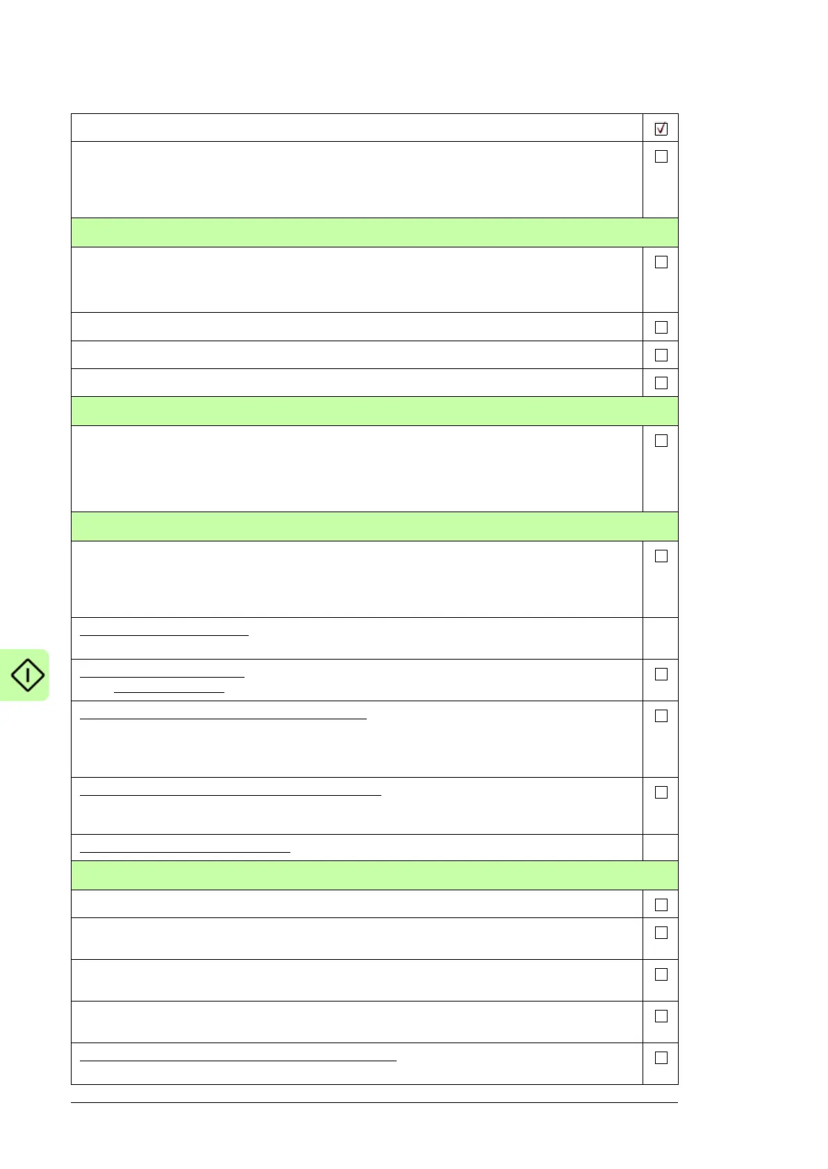
Action

 Loading...


