124 Internal control unit (option +P905)
Notes:
1)
Current [0(4)…20 mA, R
in
= 100 ohm] or voltage [ 0(2)…10 V, R
in
> 200 kohm] input selected with jumper J1. Change of
setting requires reboot of control unit.
2)
Current [0(4)…20 mA, R
in
= 100 ohm] or voltage [ 0(2)…10 V, R
in
> 200 kohm] input selected with jumper J2. Change of
setting requires reboot of control unit.
3)
Total load capacity of these outputs is 4.8 W (200 mA / 24 V) minus the power taken by DIO1 and DIO2.
4)
0 = open, 1 = closed
5)
Constant speed 1 is defined by parameter 22.26.
Further information on the usage of the connectors and jumpers is given in the sections below. For the technical data of the
connectors, see section Technical data (ZCU-12) on page 128.
Jumpers and switches
See
• page 109 for description of external power supply
• page 110 for description of AI1 and AI2 as Pt100 and KTY84 sensor inputs (XAI, XAO)
• page 111 for DI6 (XDI:6) as PTC sensor input
• page 111 for DIIL input (XD24:1)
• page 112 for Safe torque off (XSTO)
• page 112 for Safety functions module connection (X12)
• Technical data of the connectors.
Drive-to-drive link (XD2D)
The drive-to-drive link is a daisy-chained RS-485 transmission line that can be used for
• basic master/follower communication with one master drive and multiple followers
• fieldbus control through the embedded fieldbus interface (EFB), and
• drive-to-drive (D2D) communication implemented by application programming.
DI4 Ramp times according to
0 Parameters 23.12 and 23.13
1 Parameters 23.14 and 23.15
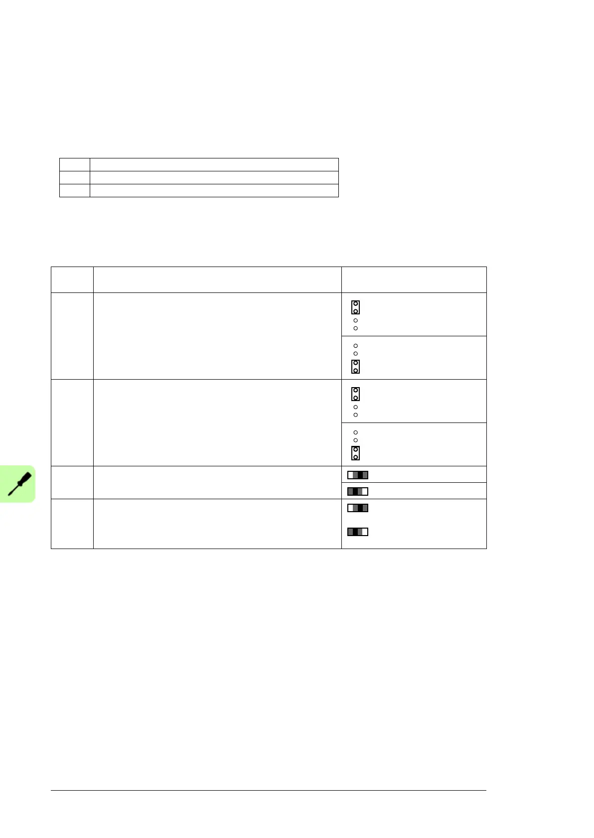
Jumper/
Switch
Description Positions
J1
(AI1)
Determines whether analog input AI1 is used as a current or
voltage input.
Current (I)
Voltage (V)
J2
(AI2)
Determines whether analog input AI2 is used as a current or
voltage input.
Current (I)
Voltage (U)
J3 Drive-to-drive link termination. Must be set to terminated
position when the drive is the last unit on the link.
Bus is terminated.
Bus is not terminated.
J6 Common digital input ground selection switch. Determines
whether DICOM is separated from DIOGND (ie, common
reference for digital inputs floats). See the Ground isolation
diagram on page 130.
DICOM and DIOGND
connected (default).
DICOM and DIOGND
separated.

 Loading...


