36 Operation principle and hardware description
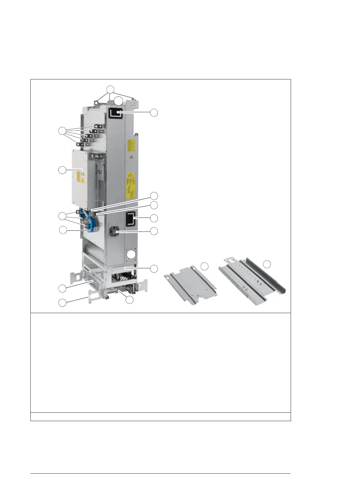
Converter module without full-size output cable connection
terminals (option +0H371) and IP20 shrouds (option +0B051) and
with common mode filter (option +E208)
1 Lifting lugs 9 Auxiliary cooling fan
2 Input cable connection busbars (L1/U1, L2/V1,
L3/W1) and DC+ and DC- busbars (UDC+,
UCD-)
10 PE busbar
3 Circuit board compartment 11 Main cooling fans
4 Output cable connection busbars (T1/U2,
T2/V2, T3/W2)
12 Base attaching screws
5 Common mode filter (option +E208) 13 Pedestal guide plate
6 Pedestal 14 Telescopic extraction and insertion ramp
7 Retractable support legs 15 Connector for charging circuit switch or
contactor
8 Handle for pulling the drive module 16 Cover. When removed, you can attach the
drive module to the LCL filter module.
Note: The front covers are removed in this photo, see number 3 on page 32.
14
13
2
1
3
6
7
4
5
12
10
11
8
8
10
9
15
16

 Loading...


