4 - 36
ABS ANTI-LOCK BRAKING SYSTEM
REMOVAL OF THE ABS HYDRAULIC UNIT
IMPORTANT NOTICE
The ABS hydraulic unit “A” has been adjusted and set with
precision by the manufacturer. Therefore it must be handled
very carefully, must never by hit for example by a hammer, or
dropped on a hard surface. Do not soak the ABS hydraulic
unit in water or mud.
• Bring the start switch to the OFF position.
Remove:
• Rider and passenger seats, see chapter “Removal of the
rider and passenger seat, Chapter 4”.
• Side fairings, see chapter “Removal of the side fairings,
Chapter 4”.
• For the fuel tank, refer to chapter “Removal of the fuel
tank, Chapter 4”.
• Discharge the brake fl uid from the front and rear brake
circuit utilising the bleed valve and pumping the brake lever
and the brake pedal.
• Do not forget to place a cloth underneath the ABS hydraulic
unit.
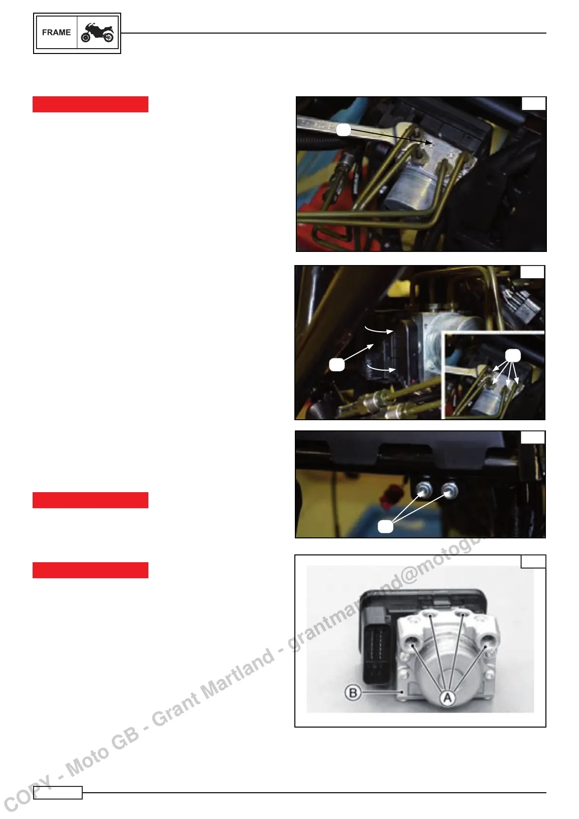
• The nuts of the rigid tubing (B). Fig. B
• the screws (D) Fig. C
Disconnect:
• The connector of the ABS hydraulic unit “C” Fig. B by rotat-
ing the lever as indicated in the fi gure.
Remove:
• Remove the ABS hydraulic unit
NOTE:_________________________________
Be careful to not bend the brake hose when removing it.
ABS hydraulic unit
• Close the oil passage holes (A) of the ABS hydraulic unit (B)
with a cloth to avoid dirt from entering into the unit Fig. D.
IMPORTANT NOTICE
Do not allow dirt to enter into the hydraulic system when the
tubes are disconnected. Brake fl uid rapidly damages paint-
ed plastic surfaces; completely wash the concerned zones
immediately.
IMPORTANT NOTICE
The ABS hydraulic unit has been adjusted and set with preci-
sion by the manufacturer.
Do not attempt to repair or remove the ABS hydraulic unit.
Check:
• Carry out a visual check of the ABS hydraulic unit.
• Substitute the ABS hydraulic unit if any component is
cracked or damaged in any way.
A
A
B
C
B
C
D
D
COPY - Moto GB - Grant Martland - grantmartland@motogb.co.uk

 Loading...