ELE. - 36
DEVICES
MASTER SWITCH
P
U
S
H
A
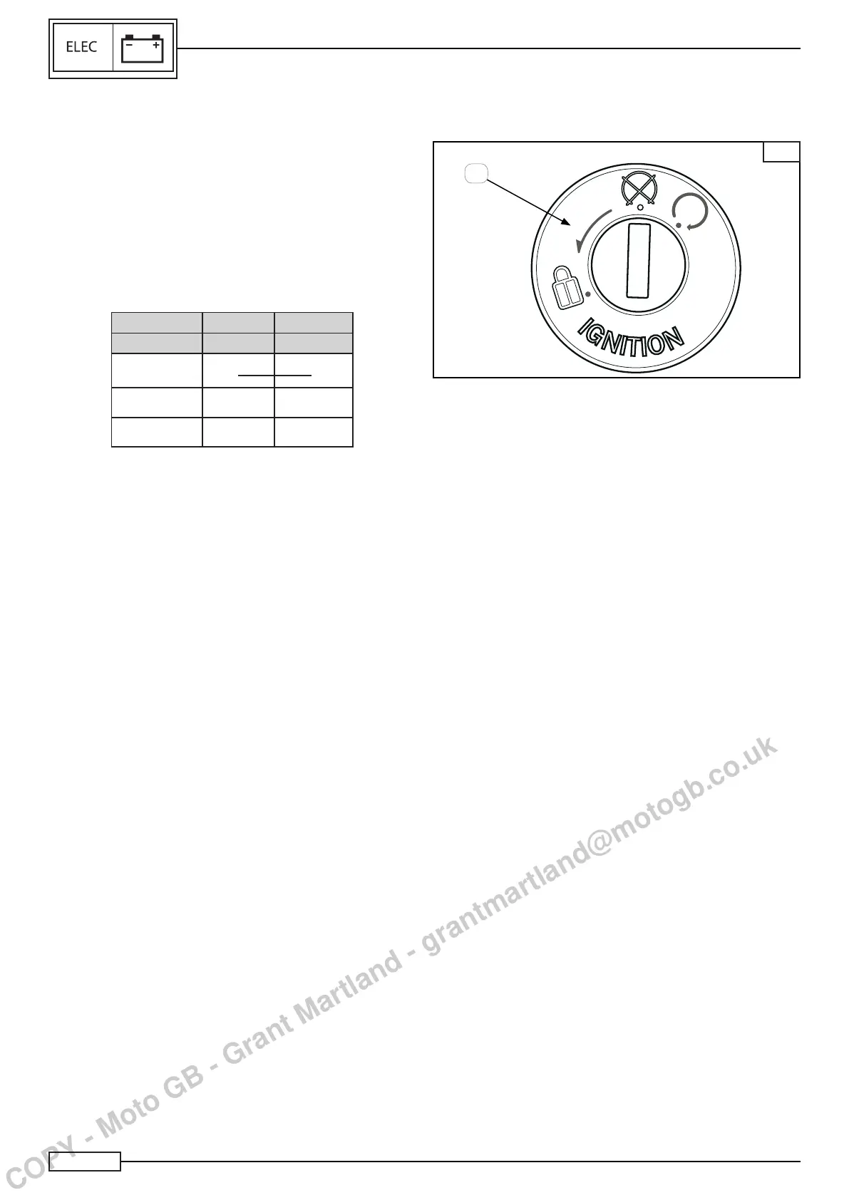
The ignition switch (1), Fig. A, is positioned behind the steering
sleeve and serves to:
• Provide the main contact to the electrical system
• Close the steering block.
• Keep the parking lights on for all conditions required.
Check:
• The continuity
using the multitester and referring to the table.
COLOUR V/G R/B
PIN PIN 1 PIN 2
Key ON
• •
Key OFF
Lock
Whentheaboveconditionsarefullled,theignitionswitchis
working properly, otherwise replace the part.
• Key in position “ON”
All electric circuits are activated, the instrumentation and the
lights carry out the self-diagnostics. The engine can be started.
The key cannot be removed.
• Key in position “OFF”
All electric circuits are deactivated, the key can be removed.
• Key in position “LOCK”
All electric circuits are deactivated and the steering is locked.
The key can be removed.
1
COPY - Moto GB - Grant Martland - grantmartland@motogb.co.uk

 Loading...