ELE. - 25
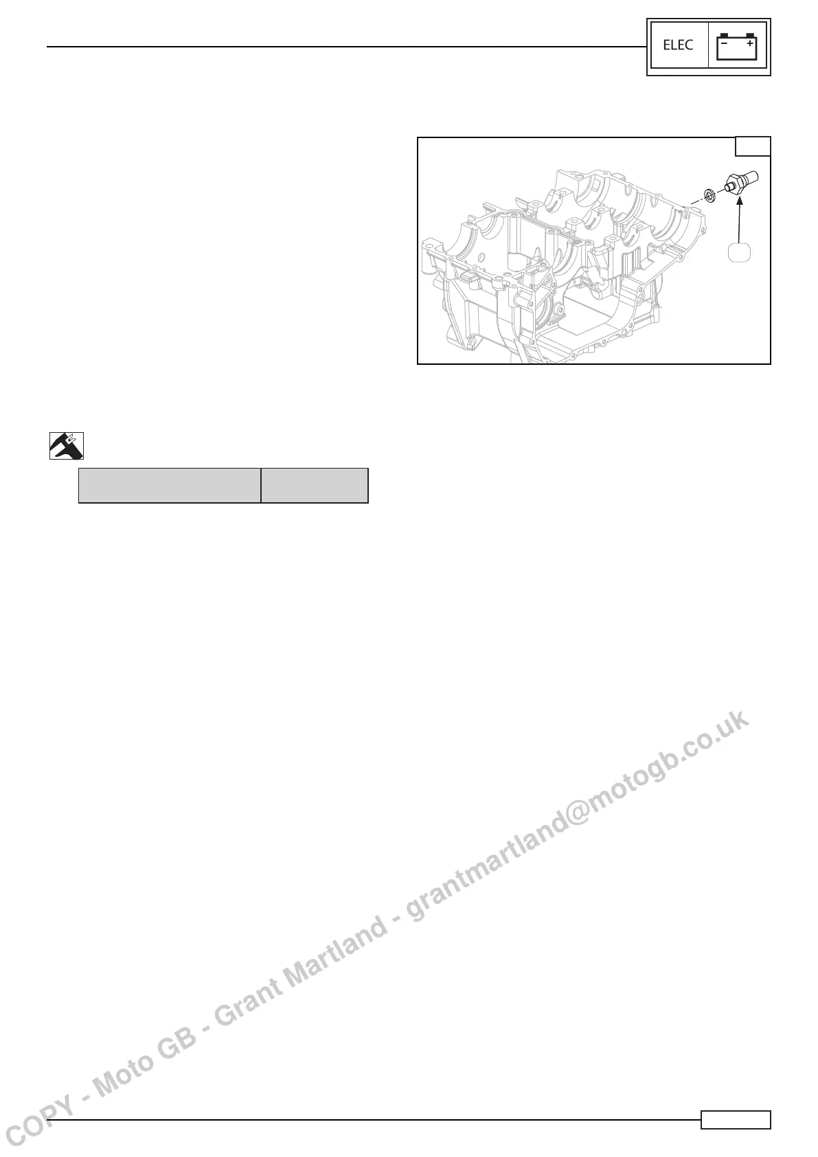
OIL PRESSURE SENSOR
It is situated on the lower half casing and measures oil pressure
in the bushing gallery (A), Fig. M.
Itindicatesthepresenceofsufcientoilpressuretothedash-
board.
Disconnect:
• The electrical coupling.
Remove:
• The oil pressure sensor
from the half casing.
Check:
• The continuity between the PIN1 and the sensor ground
by means of an air pressure regulator with insertion on the
detection hole.
• Set the air pressure regulator at 2 bar.
• Reduce pressure gradually to reach 0.2 - 0.3 bar.
Continuity between PIN1 and
ground
0.2 - 0.3 bar
NOTE:________________________________
If there is no continuity between PIN1 and engine ground,
replace the part.
M
A
SENSORS
COPY - Moto GB - Grant Martland - grantmartland@motogb.co.uk

 Loading...