ELE. - 45
SERVICES RELAY
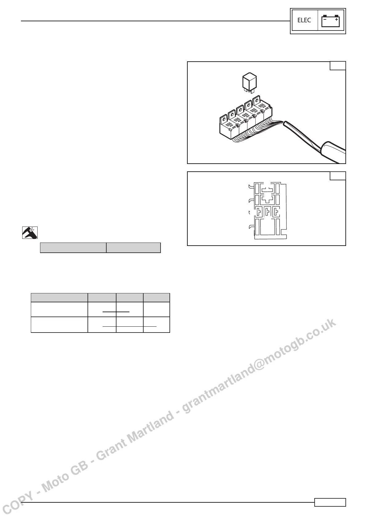
It is situated inside the storage compartment, underneath the ve-
hicle seat (Fig. A). The relay assembly is managed by the ECM
to control each load at best, such as:
• The lighting system
The ECM ensures that the lights turn on in certain conditions.
• The fuel pump
The fuel pump is activated only when the starter lets the engine
rotate.
• The electric fans
• The injection
The ECM controls the injection relay pull-in according to the
relevant conditions, as ignition, shutdown, and use of the vehi-
cle, thus allowing a stable supply to ECM, which can carry out
any correct procedure of storage and setting of the parameters
in the standstill phase, by continuing its self-powering for some
seconds after the instrument panel shutdown.
• Services
All devices “with ignition on”, as dashboard, various safety devic-
es and lighting system, are connected to the services relay.
Check:
• Theresistanceusingthemultitesteronsymbol“Ω”between
pin 85 and pin 86 (Fig. B).
Resistance
12 ± 2 Ω
Use:
• The tester and, referring to the table, check on relay pins,
by powering the PIN 85 and the PIN 86 to the battery.
RELAY PIN 87 PIN 30 PIN 87A
Powered on battery
• •
Not powered on
battery
• •
NOTE:________________________________
When the above conditions are fullled, the relays are oper-
ating properly, otherwise replace the parts.
A
30
87
85
87
86
B
DEVICES
COPY - Moto GB - Grant Martland - grantmartland@motogb.co.uk

 Loading...