ELE. - 33
DEVICES
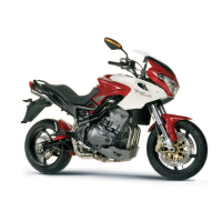
STARTING RELAY (REMOTE CONTROL SWITCH)
It is situated close to the fuse block and breaks power contact
on the starter (1) Fig. A.
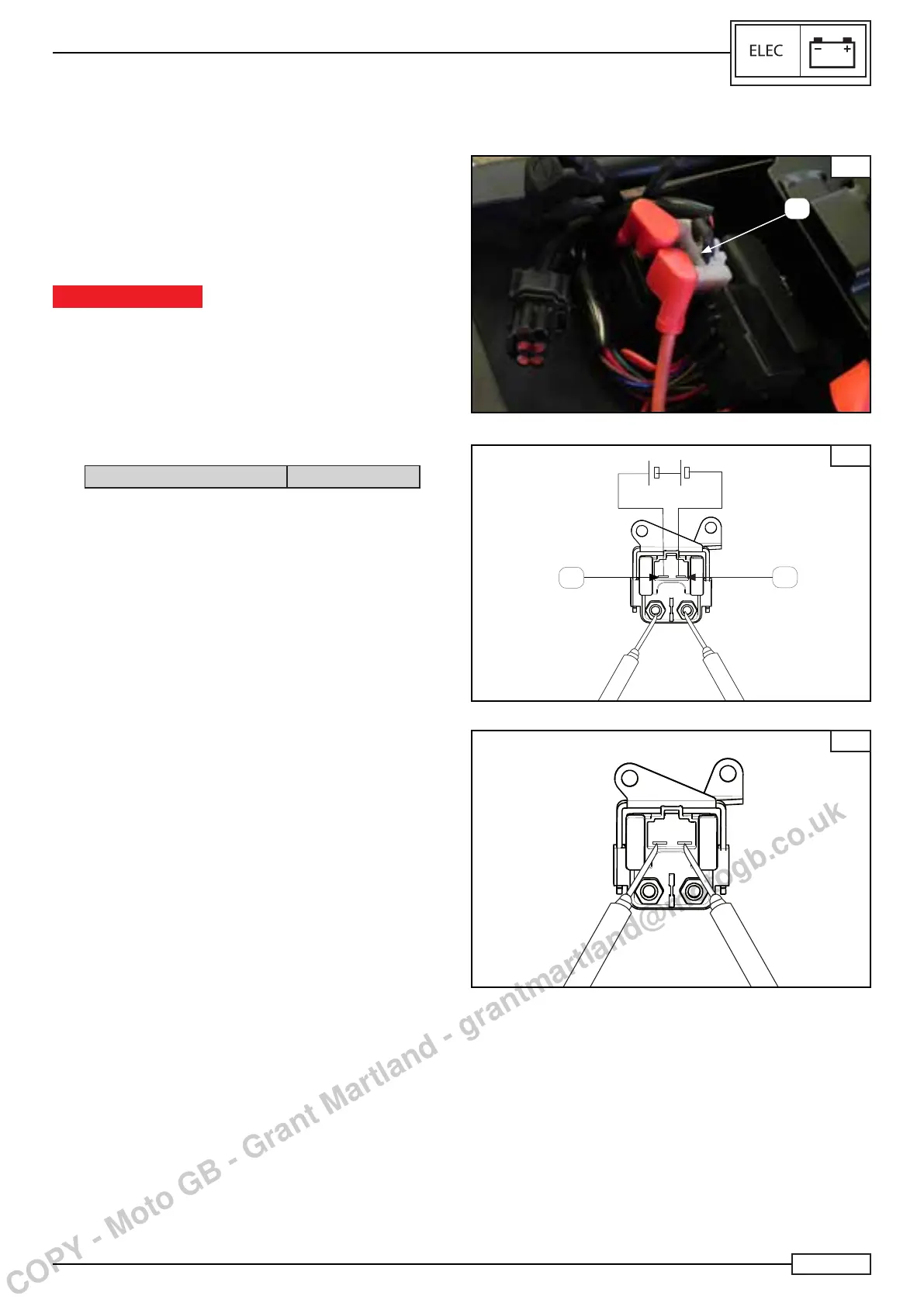
Apply:
• 12 volt to terminals (2) and (3) Fig. B
Check:
• The continuity between power terminals.
In presence of continuity, the starter relay works properly.
WARNING
Do not apply the battery voltage to the starter relay for more
than 5 seconds to prevent overheating and damages to
winding.
Check:
• If the winding Fig. B.
is “open” or “grounded” and if there is resistance.
The winding is in good working order if the resistance is:
Starting relay resistance 3 - 6 Ω
A
1
B
3
2
B
COPY - Moto GB - Grant Martland - grantmartland@motogb.co.uk

 Loading...