EasyManuals Logo
Home>Benelli>Motorcycle>TRK 502

Benelli TRK 502 Service Station Manual

Benelli TRK 502
408 pages
To Next Page IconTo Next Page
To Previous Page IconTo Previous Page
Page #319 background imageLoading...
Page #319 background image
5 - 66
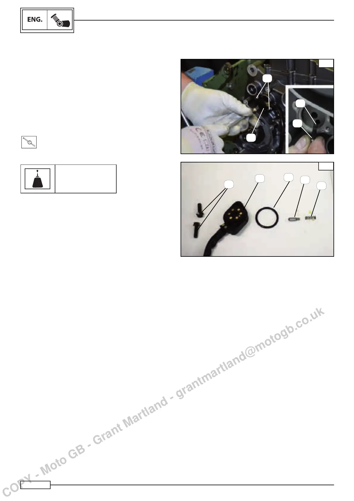
NEUTRAL POSITION/GEAR INDICATOR SENSOR ASSEMBLY
Assemble:
insert the spring (2) Fig. A
the pin (3) Fig. A
the gasket (4) Fig. B
the neutral position/gear indicator sensor (1).
NOTE:_________________________________
Before assembly, check the continuity of the sensor (see
the chapter entitled “Electrical system”)
Tighten the two screws (5) of the sensor to the following torque:
T
.
R
.
Torque 0.6 N*m
Use Loctite
Loctite 243
GEAR BOX
A
1
B
1
2
3
3
2
4
5
5
COPY - Moto GB - Grant Martland - grantmartland@motogb.co.uk

Table of Contents

Other manuals for Benelli TRK 502

Questions and Answers:

Question and Answer IconNeed help?

Do you have a question about the Benelli TRK 502 and is the answer not in the manual?

Benelli TRK 502 Specifications

General IconGeneral
BrandBenelli
ModelTRK 502
CategoryMotorcycle
LanguageEnglish

Related product manuals