—————— TPD32-EV ——————
130
Voltage regulator in the field converter
note! InthemostofthecasestheDCmotorswithanindependentexcitationoperatewithadirect
eld(Flux reg mode=Constant current).Inthiscaseitisnotnecessarytooptimizethe
regulatorofthearmaturevoltage.
WhenaVoltagecontroloccurs,thevoltageregulatorkeepsthearmaturevoltageataconstantlevel.Themost
difcultmomentforthisregulatoristhebeginningoftheVoltagecontrol,becauseduetothesaturationofthe
motoreld,theuxvariationrequiresquickerchangesoftheeldcurrent.
Tunetheregulatorinordertohavesmallchangesofthearmaturevoltage.
note! Alltheotherconverterregulatorsmustbesetbeforetheoptimizationofthevoltageregulator.
- Drivedisabled=novoltageonterminal12
- ChoosethefollowingsettingsfortheTestgenerator:
- Gen access = Rampref
- Gen frequency = 0.2Hz
- Gen amplitude = 10%
- Gen offset = accordingtothechangingpointfromthearmatureregulation
totheeldone.Example:Motor max speed=2000rpm,
theVoltagecontrolstartsat1500rpm.Gen offset=75%
- Measuretheeldcurrentandthearmaturevoltageonananalogoutput.The“Fluxcurrent”andthe“Output
voltage”variablesmustbesetontwodifferentanalogoutputs(seeProgramming“Inputs/Outputs).
- EnablethedriveandgivetheStartcommand(voltageontheterminals12and13)
- Checkthearmaturevoltage.Afterapossibleshortjump,thevoltageshouldremainconstant.Seegures
5.3.6.8...5.3.6.10.IntheREGPARAMETER/...menu,itispossibletochangethePandIsectionwith
theVoltage PandVoltage I parameters.
- Stopanddisablethedrive.
- Genaccess=Notconnected
- Savethesettings.
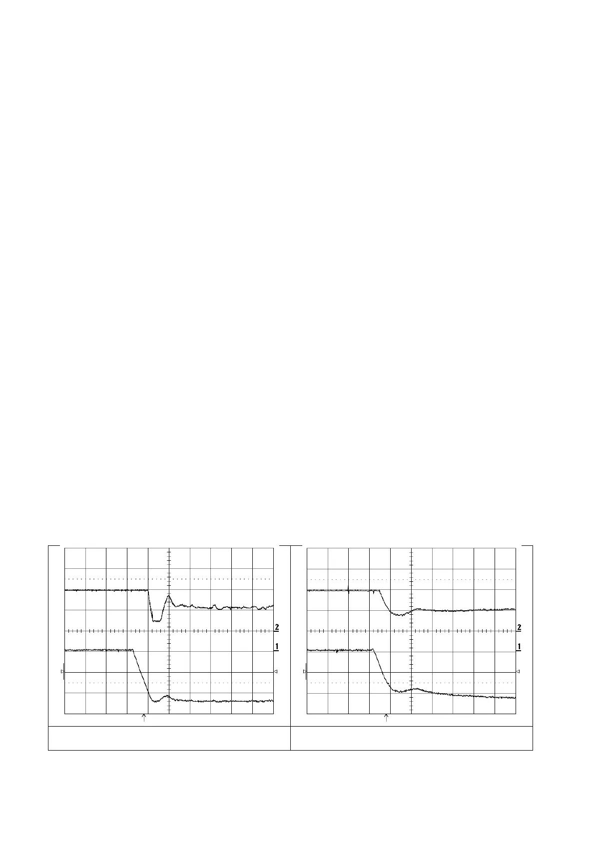
Figure 5.3.6.8: Above: Flux; Below: Output voltage. After a speed change the
field current (Flux) has some jumps. Voltage P = 10%, Voltage I = 80%.
Figure 5.3.6.9: Above: Flux; Below: Output voltage. The gain is too low. The
armature voltage increases. Voltage P = 3%, Voltage I = 5%.
 Loading...


