—————— Instruction manual ——————
333
Control of the speed reference
Inordertocalculatethespeedreferenceduringthedifferentfunctioningphasesofthemachine,astatuslogic
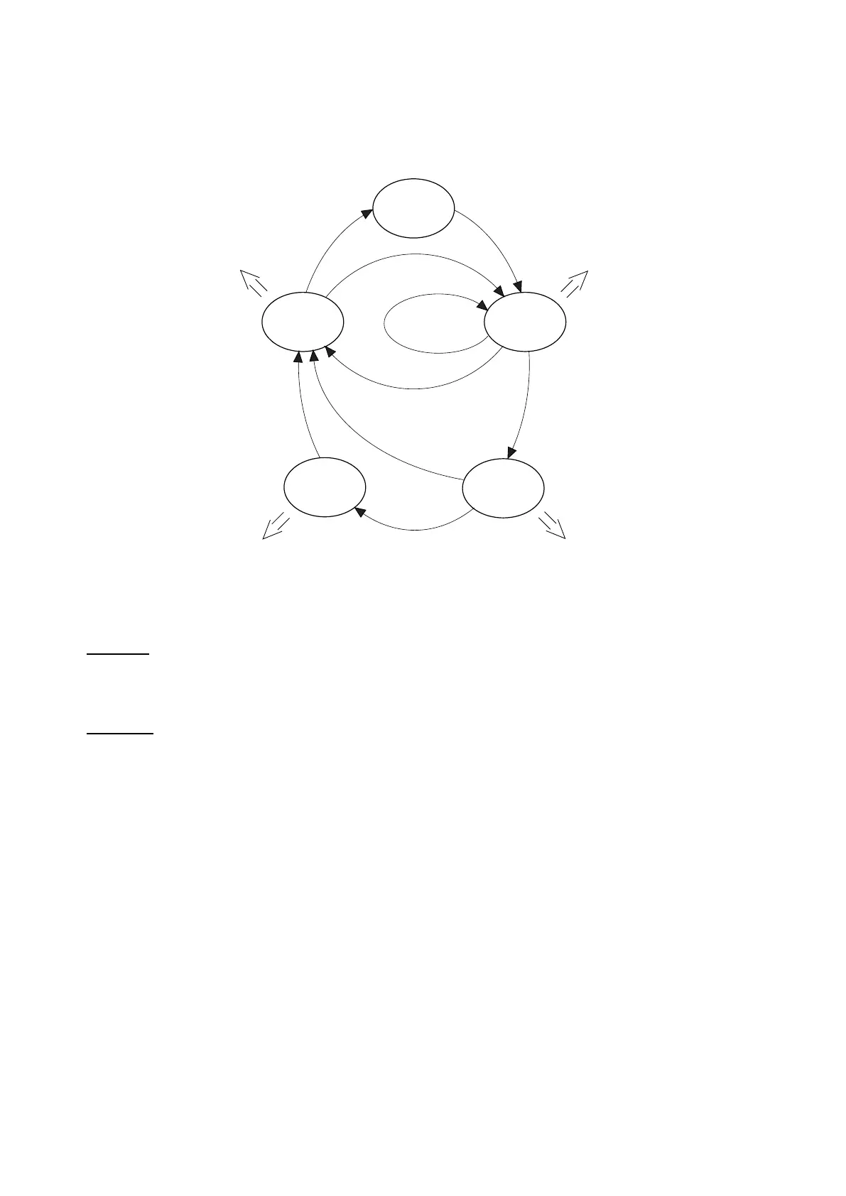
hasbeendeveloped.Thestatussequenceandtheoperativenessisdescribedinthegure6.17.3.
Status 1
(default)
Status 2
Status 3
Status 4
Status 5
Start (drive) = 1
Start (drive)=1
Start (drive)=0
Start (drive) = 0
Start (drive)=0
Speed match=1
Speed match=0
Speed 0 thr = 1
Int acc time=0
Int dec time=0
Int offset acc time=Offset acc time
Intwoffset=Woffset
Int acc time=Spd match acc
Int dec time=0
Int offset acc time=0
Intwoffset=0
Int acc time=0
Int dec time=Spd match dec
Int offset acc time=0
Intwoffset=0
Int acc time=0
Int dec time=0
Int offset acc time=0
Intwoffset=Woffset
Figure 6.17.3: Operative sequence of the functioning status
Status 1:
Defaultstatus,thissystemconditionisgivenwhenthedriveisinaStopcondition.Thespeedreferenceiszero.
Status 2:
ThesystemreachesthisstatuswhentheStartcommandisgiven.
Whenthelineisstopped,theinitialphasereferenceW offset isassignedwiththeramptimeOffset acc time.
Whenthelineisstarted,themotorspeedreferencefollowsitsprolewithavaluecorrespondingto:
W reference = ± Line speed x (Minimum diameter ÷ Roll diameter) ± (W gain % + W offset)
thesignof:
± Line speed x (Minumum diameter ÷ Roll diameter)
ispositiveifWind/unwind=winder
isnegativeifWind/unwind=unwinder
thesignof:
± (W gain % + W offset)
isusuallypositive,itcouldbechangedonlyifduringtheaccelerationordecelerationphasesatorqueinver-
sionisrequired.
ThepolarityofW referencewillbefurtherinvertedifWinder side=1
(winding/unwindingdown).
IfduringaStatus1functioningperiodthesystemreceivesaStopcommand(Startdrive=0),theStatus5is
forced.
 Loading...


