—————— TPD32-EV ——————
82
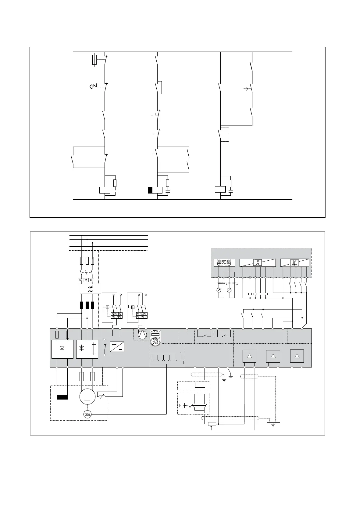
4.8 STANDARD CONNECTION DIAGRAMS
Emergenza
Emergenza
K0
Q2
F2
Termica motore
S11
Off / Stop
S2
On / Start
On / Off
Start / Stop
K2
K0
K2
K1M
Rete
Nota !
Q2 per ventilatore sulle
taglie a partire da 770 A
L01
L00
35
36
K1M
K1M
K0
G1
ok
[P412]
K2
t > t
br
K0
Cavallotto: frenatura d'emergenza,
disinserzione a motore fermo
Senza cavallotto: disinserzione
diretta, il motore si ferma per inerzia
75
76
G1
Stop control
[P629]
G1
(a partire da 770 A)
Q1
Alimentazione
regolazione
81
82
K1M
K2
Figure 4.8.1: Control sequencing
+ 24V
V3
U3
W
V
U
M1
K1M
5
F11
L1
L2
L3
N
PE
K2
F2
C
D
0 V24
1
2
3
4
6
PE
K1M
A+
A-
B+
B-
K0
Q1
1
3
5
24
6
(1)
L1
Thermistor (3)
78
79
1
5
6
2
8
7
0V
24V
XE2
COM ID
19
18
16
15
External
Fault
14
13
12
Fast stop
Start
Enable
drive
35 (6)
36
75 76
ok [P412]
Relay 2 [P629]
RS 485
Keypad
7
8
9
+ 10 V
- 10 V
0 V 10
0 V
0
Rigth
Left
R1 (2 ... 5 kOhm)
2
1
3
4
5
6
Analog input 1
Analog input 2
-
-++
Analog input 3
-
+
(4)
W1
TPD32...2B
TPD32...4B
1
3
5
24
6
Q2
F12
V1
U1
D1
C1
1F1
2F2
1B1 2B2
F3
(2)
PE
PE
U2
V2
11
G1
M
SMPS
81
82
(5)
Analog outputs
12
21 22 23 24
Digital outputs
1234
25 26 27 28 29 30
Supply
Digital inputs
37 31 32 33 34
1234
0 V
+ 24 V
F13
M1-M2
115 - 230 V
AC
230 V
AC
EMC FILTER
M- M+ AL EN n=0 Ilim
E
CANC
–
+
Figure 4.8.2: Typical connections
Typicalwiringdiagramforthestandardcongurationoftheconverter.
Itisnecessarytofollowtheinstructionsformountingandwiringgiveninthechapters
concerningengineeringnotesandEMCmeasures.
Optioncardsconnectionisnotindicatedhere.
Itisnotconsideredtheautorestartofthedriveafteranalarmcondition.
(1)Externally-poweredfanunitswithtypesCandDonly.
(2)FusesforTPD32-EV...4BtypesAandBonly.
(3)1Kohmresistorconnectedwhenthethermistorisnotpresent.
(4)TheindicatedconnectionsarerelativeforadigitalEncoder.
(5)TypesCandDonly.
(6)OnthePower/Controlcard“FIR...”.
Connectionsforsinusoidalencoderandtachogeneratorareseratelyindicated.
 Loading...


