—————— TPD32-EV ——————
272
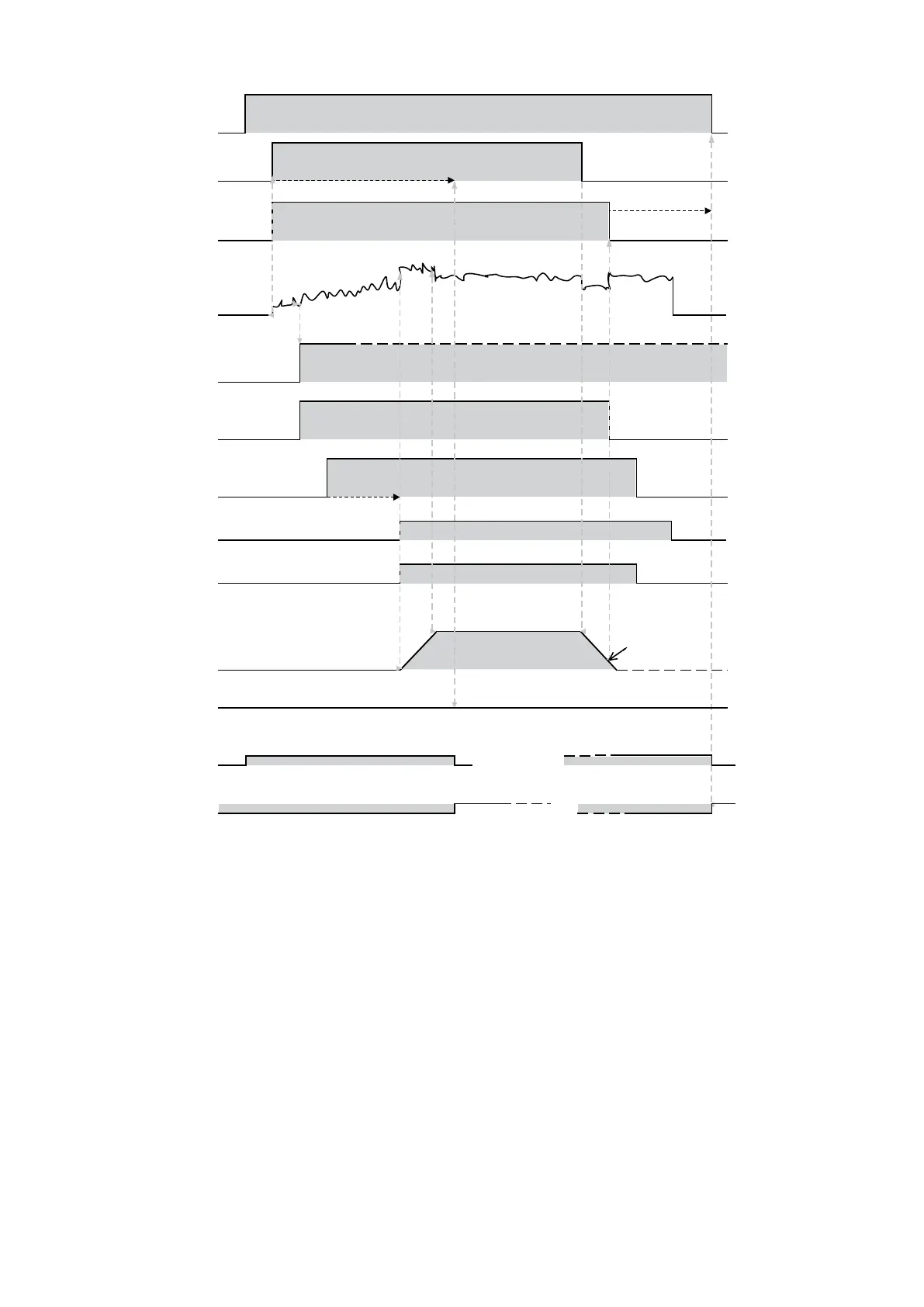
RUN
START
Torque front monitoring time
T =1sec
Brake drop
out speed
detection
Brake
release
current
detection
Brake
switch
command
Brake
switch
feedback
Actuator delay
time
Actual
opening
of brake
pads
Ramp
validation
Speed
feedback
Brake drop out threshold
Switch
delayed
feedback
Inverter
locking
Engaging fault
Mechanical
brake
fault
Figure 6.14.8.1: Diagram of control
Diagram of control
Functionaldiagramwithminimaluseofinputsandoutputs.Specicassignmentsofthisdiagram:
DI1: FwdsignAscending,conventionally“Forward”
DI2: RevsignDescending,conventionally“Reverse”
DI3: Brakefbk,mechanicalbrakefeedback/relaystatus
Relay2: BrakecommandKM10contactorcommand
Withreferencetothepreviousgraph,abrakealarmconditionoccursif:
- when the brake is released,followingtheEnableandStartcommands,thevalueofthecurrentsuppliedby
thedriveisunabletosustaintheload(indicatedbytheTorqueprovingparameterandsignalledbythebrake
commanddigitaloutput)inatimethatislessthantheTorquedelaytime;or,ifthecurrentisadequate,the
signalconrmingthatthebrakehasbeenreleased(Brakefbk)hasnotbeenreceived,againwithinthetime
setinTorquedelay.
- when the brake is closed,oncethespeedsetintheClosingspeedparameterhasbeenreached(signalled
 Loading...


