—————— TPD32-EV ——————
26
2.3 SPECIFICATIONS
2.3.1 Standards
General: EN61800-1,EN60146-1-1.
Safety: EN61800-5-1,EN50178
Clearancesandcreepagedistances:
Overvoltagecategoryforcircuitsconnecteddirectlytothemains:III;pollutiondegree:
2.Doubleorreinforcedinsulation/safeseparationfromlivepartsofdecisivevoltage
classC;seeEN61800-5§4.2.3.
Oscillationtest: EN60721-3-3class3M1,EN60068-2-6,testFc.
Climaticconditions: EN60721-3-3,class3K3.EN60068-2-2,testBd.
EMC:
EN61800-3.See“
Guidetotheelectromagneticcompatibility
”.
Ratedmainsvoltage: IEC60038.
Protectiondegree: AccordingtoEN60529,
IP20fortypesA,B,C;IP00fortypesDandE.
UL/cULapproval: ForTPD32-EV-…-NAmodels(sizesTPD32-EV-…-E-NAnotincluded).
attention! TheDCdriveissuitableforuseundertheenvironmentalserviceconditions(climate,me-
chanical,pollution,etc.)denedasusualserviceconditionsaccordingtoEN61800-1.
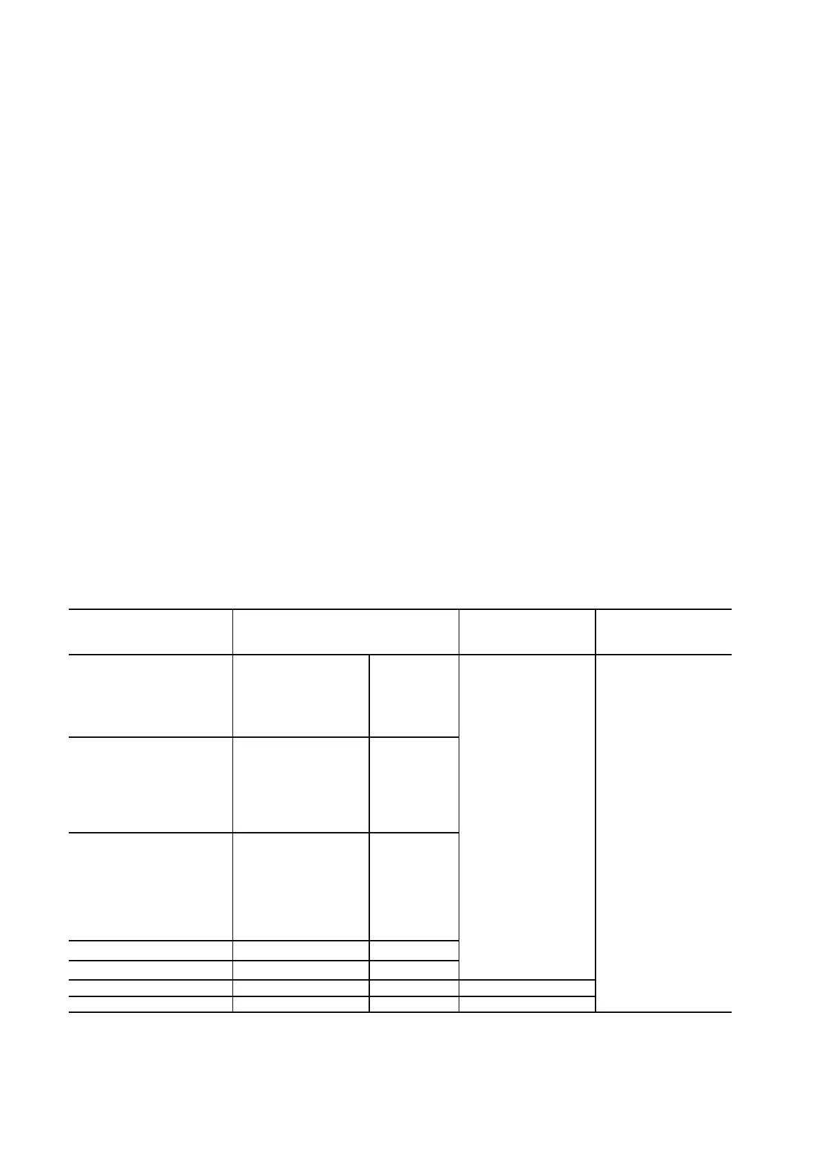
2.3.2 AC Input
Table 2.3.2.1: AC input voltages
DC Drive series Power section
(U/V/W terminals)
Field circuit Power supply regulation
section
(U1/V1 terminals) (U2/V2 terminals)
TPD32-EV-500/...
3 x 230 V ±10 %*
3 x 400 V ±10 %*
3 x 440 V ±10 %*
3 x 460 V ±10 %*
3 x 480 V ±10 %*
3 x 500 V ±10 %*
50/60 Hz ±5 %
1 x 230 V ±10 %*
1 x 400 V ±10 %*
1 x 460 V ±10 %*
50/60 Hz ±5 %
1 x 115 V ±15 % **
or
1 x 230 V ±15 % **
50 / 60 Hz ±5 %
TPD32-EV-575/...
3 x 230 V ±10 %*
3 x 400 V ±10 %*
3 x 440 V ±10 %*
3 x 460 V ±10 %*
3 x 480 V ±10 %*
3 x 500 V ±10 %*
3 x 575 V ±10 %*
50/60 Hz ±5 %
TPD32-EV-690/...
3 x 230 V ±10 %*
3 x 400 V ±10 %*
3 x 440 V ±10 %*
3 x 460 V ±10 %*
3 x 480 V ±10 %*
3 x 500 V ±10 %*
3 x 575 V ±10 %*
3 x 690 V ±10 %*
50/60 Hz ±5 %
TPD32-EV-CU-230/500-THY.-.. 3 x 230...500V ±10 % 50/60 Hz ±5 %
TPD32-EV-CU-575/690-THY.-.. 3 x 575...690V ±10 % 50/60 Hz ±5 %
TPD32-EV-FC-200/... 3 x 60...200V ±10 % 50/60 Hz ±5 % -
TPD32-EV-FC-500/... 3 x 230...500V ±10 % 50/60 Hz ±5 % -
* WiththeindicatedtolerancevaluestheoutputvoltagecompliestheDIN40030standard.
Withwidertolerancesthemaxoutputvoltagechengesaccordingly.
** For operation at 115 V, from sizes 280 A to 1050 A, insert a jumper between terminals SA – SB located at the top of the converters.
 Loading...


