—————— TPD32-EV ——————
268
Example
Motor P=30kW,Armaturevolts=420V,Armaturecurrent=82A
Loadcycle Themotorisoverloadedfor1sat180%oftheratedcurrent,thenitworksattherated
loadforatleast5s.Fourquadrantconverter.
Procedure Atrstselectthedccurrentaccordingtothemotorratedcurrent.Usuallyitisthemotor
ratedcurrent.IfthedeterminedmotoroperatingpointisnotbelowtheOverloadcurve
oftheconverter,thecalculationshouldberepeatedwiththenextlargerconvertersize.
Converter TPD32-EV-500/520-110-4B-A
Diagram
= 0.75
for05
Base current
I
dAN
82 A
110A
=
Thismeansthatthediagramfortheconverters110A...185AwithaBasecurrent=75
%hastobeconsideredforthecalculation.
Operatingpoint Basis:rateddataoftheconverter
Overload current=82A . 1.8=147.6A
for06
= 1.34
for07
Overload current
I (of converter)
dAN
147.6 A
110A
=Overload factor =
= 0.16
for08
Overload time
Pause time+Overload time
1s
5s+1s
=
1s
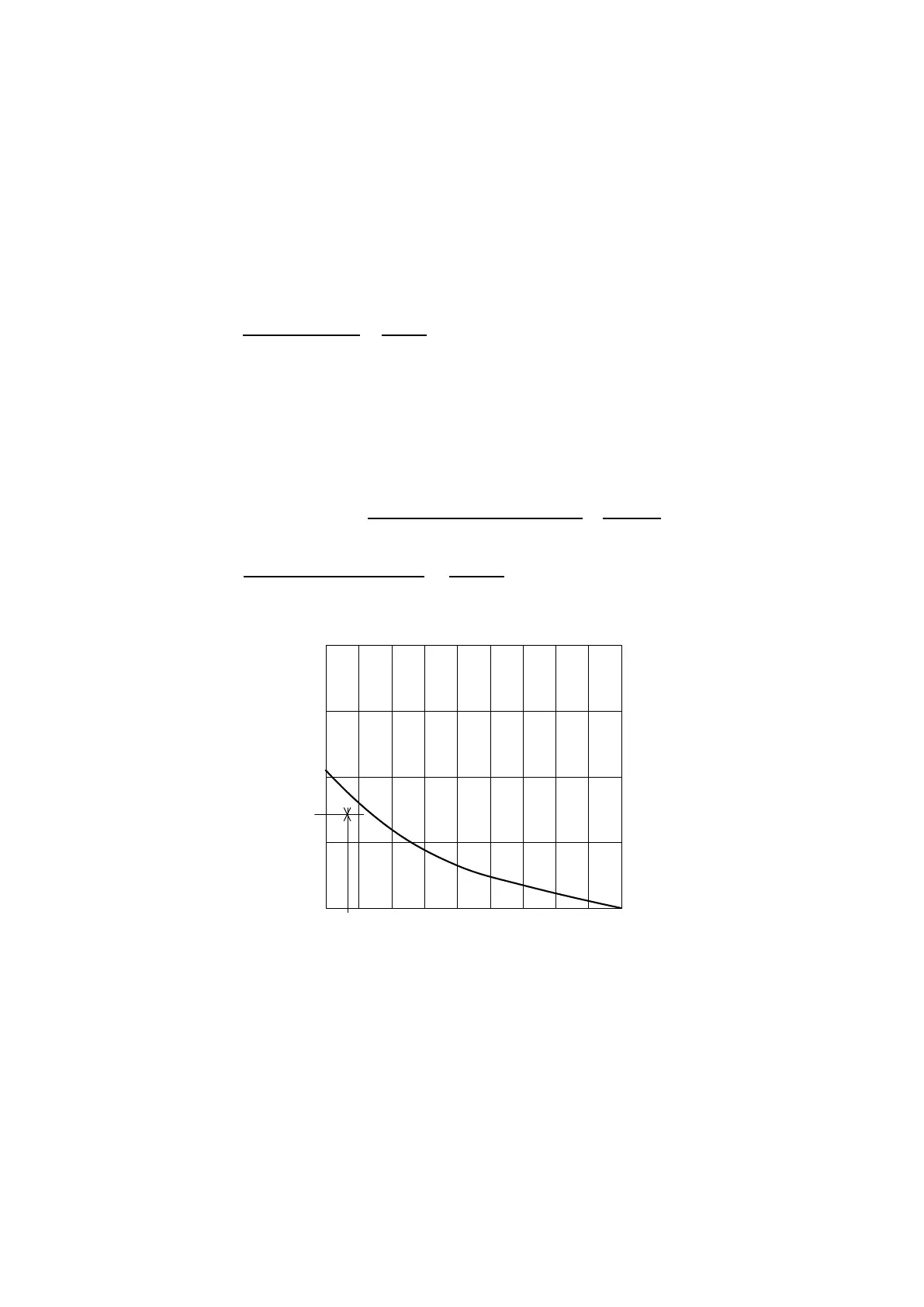
Base current=75%I
2,00
1,75
1,50
1,25
1,00
Overload current / I
dAN
dAN
0,1 0,2 0,3 0,4 0,5 0,6 0,7 0,8 0,9 1,0
Overload time/(Pause time+Overload time)
Overload time
Figure 6.14.6.3: Example- Operating point of drive
Thecalculatedoperatingpointisbelowthecorrespondingcurveforanoverloadtimeof1s.Thereforethecon-
verterissuitablefortheapplication.Thefollowingtwosettingsarepossible:
Full load curr 82A or 110A
Enable overload Enabled
Overload current 180% or 134%
Base current 100% or 75%
Overload time 1s
Pause time 5s
note! ThepercentagesforOverload currentandBase current arereferredto Full load currand
nottotheconverterratedcurrent!
 Loading...


