—————— Instruction manual ——————
477
A1.3 Choosing the right model for your application
TPD32-CU-230/500-THY1-FC70
TPD32-CU-230/500-THY1-FC40
TPD32-CU-230/500-THY2-FC70
TPD32-CU-230/500-THY2-FC40
TPD32-CU-575/690-THY1-FC70
TPD32-CU-575/690-THY1-FC40
TPD32-CU-575/690-THY2-FC70
TPD32-CU-575/690-THY2-FC40
230V
AC
to 500V
AC
above 500V
AC
to 690V
AC
1 2
70A40A
START
Powerbridge
mains voltage value
SCRinparallelon each
legof powerbridge
SCRinparallelon each
legofpower bridge
1 2
Maxmotor
fieldcurrent
Maxmotor
fieldcurrent
Maxmotor
fieldcurrent
Maxmotor
fieldcurrent
40A 70A 40A 70A 40A 70A
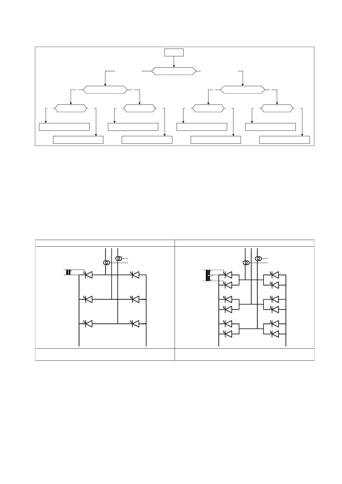
Theowchartillustratesthechoiceofunit,basedontheratedsupplyvoltage,theneedtocontrolpulsetrans-
formerswithoneortwosecondarywindingsandthemaximumeldcurrentrequested.
Thereisnoneedtomakeadistinctionbetweentwoorfour-quadrantdrives;thisisdonebyconguringjumper
S1ontheFIRXP-XXpowercard.ON=4Q(default),OFF=2Q(seeFigure11.3.5).
ThecontrolunitiscapableofcontrollingSCRpowerbridgeswithfourpossiblecongurations,whichmustalso
betakenintoaccountwhenchoosingtheappropriateCUwiththerelativeconnectioncablesandpulsetrans-
formers.Thesefourpossiblecongurations,referringtotwo-quadrantbridges,areillustratedbelow(thesame
choicesapplytofour-quadrantbridges).Likewise,themainsvoltageandmax.eldcurrentarenotconsidered..
Configuration 1: Single bridge with 1 SCR per branch Configuration 2: 1 single bridge with 1 SCR per branch in parallel
...
This is regarded as a standard configuration that can be achieved with a
TPD32-EV-CU-XXX/XXX-THY1-XX control unit and the cables supplied with it.
This is achieved with the TPD32-EV-CU-XXX/XXX-THY2-XX control unit and
the cables supplied with it
 Loading...


