111
FX3UC Series Programmable Controllers
User’s Manual - Hardware Edition
3 Generic Specifications/Installation Work
3.4 Connection between main unit and extension equipment
1
Outline
2
External
Dimensions
3
Generic
Specifications
4
Power Supply
Specifications
5
Input
Specifications
6
Output
Specifications
7
Examples of
Wiring for
Various Uses
8
Terminal Block
9
CC-Link/LT
Master FX
3UC
-LT only
10
Display module
FX
3UC
-LT only
1
Outline
2
External
Dimensions
3
Generic
Specifications
4
Power Supply
Specifications
5
Input
Specifications
6
Output
Specifications
7
Examples of
Wiring for
Various Uses
8
Terminal Block
9
CC-Link/LT
Master FX
3UC
(LT only)
10
Display module
FX
3UC
(LT only)
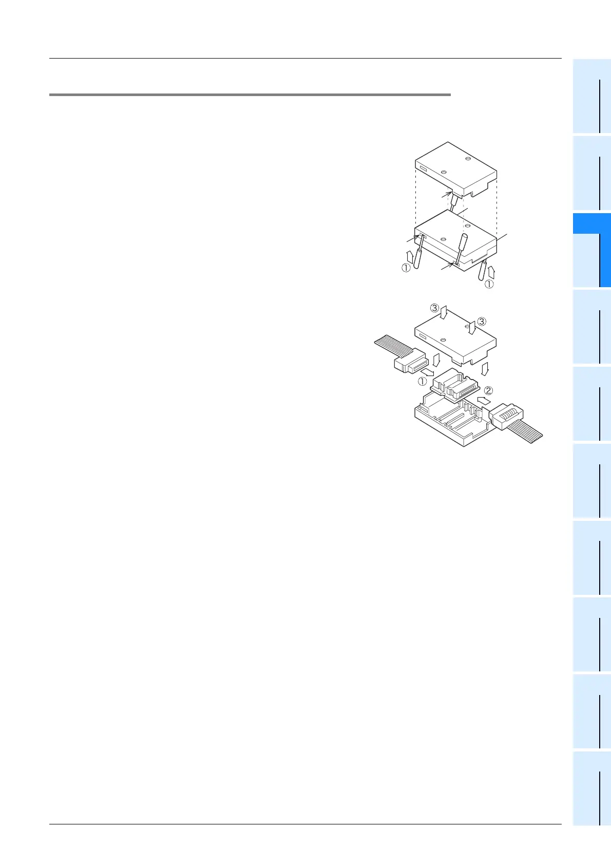
3.4.4 Connecting method C (Extension cable • FX2N-CNV-BC connecting)
This subsection explains the procedures for connecting an extension cable and FX2N-CNV-BC to the
extension cable of the extension unit/block.
1. Connection procedure
1) Separate the case of FX2N-CNV-BC into two pairs as
shown right.
To separate the case, use a precision flathead
screwdriver. Slightly insert the tip of the screwdriver
into the part A shown in the right figure, and the hook
will come off (4 places).
2) Connect the extension cable on the upstream side
(
c
in the right figure).
3) Connect the extension cable on the downstream side
(
d
in the right figure).
4) Fit the upper cover and the lower cover (
e
in the right
figure), and press down the upper cover until it is
hooked.
Hook
A
A
A
A
Upstream
extension cable
Downstream
extension cable
FX
0N-30EC
FX
0N-65EC
 Loading...


