243
FX3UC Series Programmable Controllers
User’s Manual - Hardware Edition
8 Terminal Block Specifications and External Wiring
8.13 FX-16EYS-TB
1
Outline
2
External
Dimensions
3
Generic
Specifications
4
Power Supply
Specifications
5
Input
Specifications
6
Output
Specifications
7
Examples of
Wiring for
Various Uses
8
Terminal Block
9
CC-Link/LT
Master FX
3UC
(LT only)
10
Display module
FX
3UC
(LT only)
8.13 FX-16EYS-TB
Connect the FX-16EYS-TB to the output connector in the main unit or extension block shown in the table
below.
The applications shown below are not supported.
8.13.1 Specifications
*1. In systems where frequent large-load ON/OFF switching occurs due to rush currents, the root mean
square current should be 0.2A or less.
*2. This response time does not include the response delay at the PLC.
Output connector
Connectable models FX
3UC-MT/D, FX3UC-32MT-LT, FX2NC-EYT, FX2N-16EYT-C
Unsupported Applications
Pulse output
Pulse Y output (PLSY) instruction, acceleration/deceleration setup (PLSR) instruction, pulse
width modulation (PWM) instruction, DOG search zero return (DSZR) instruction, interruption
positioning (DVIT) instruction, batch data positioning mode (TBL) instruction, absolute current
value read (ABS) instruction, zero return (ZRN) instruction, variable speed pulse output (PLSV)
instruction, drive to increment (DRVI) instruction, drive to absolute (DRVA) instruction
Time division input
Input matrix (MTR) instruction, hexadecimal input (HKY) instruction, digital switch (DSW)
instruction, arrow switch (ARWS) instruction
Time division output Seven segment with latch (SEGL) instruction, print (ASCII Code) (PR) instruction
Item FX-16EYS-TB
Connection form
Terminal block (M3.5 screw)
The connection with the PLC is the connector.
Output type Triac (SSR)
External power
supply
85 to 242V AC
Max.
load
Resistance
load
0.3 A/point
*1
Make sure that the total load current of 4 resistance load points is 0.8A or
less.
Inductive load
15 VA/100V AC
36 VA/200V AC
Min. load
0.4 VA/100V AC
1.6 VA/200V AC
Open-circuit leakage
current
1mA/100V AC
2mA/200V AC
Response time
*2
2ms or less
Circuit isolation Photocoupler isolation
Operation indicator LED lights when photo-thyristor power is supplied
Power consumption 2.7 W (112mA 24V DC)
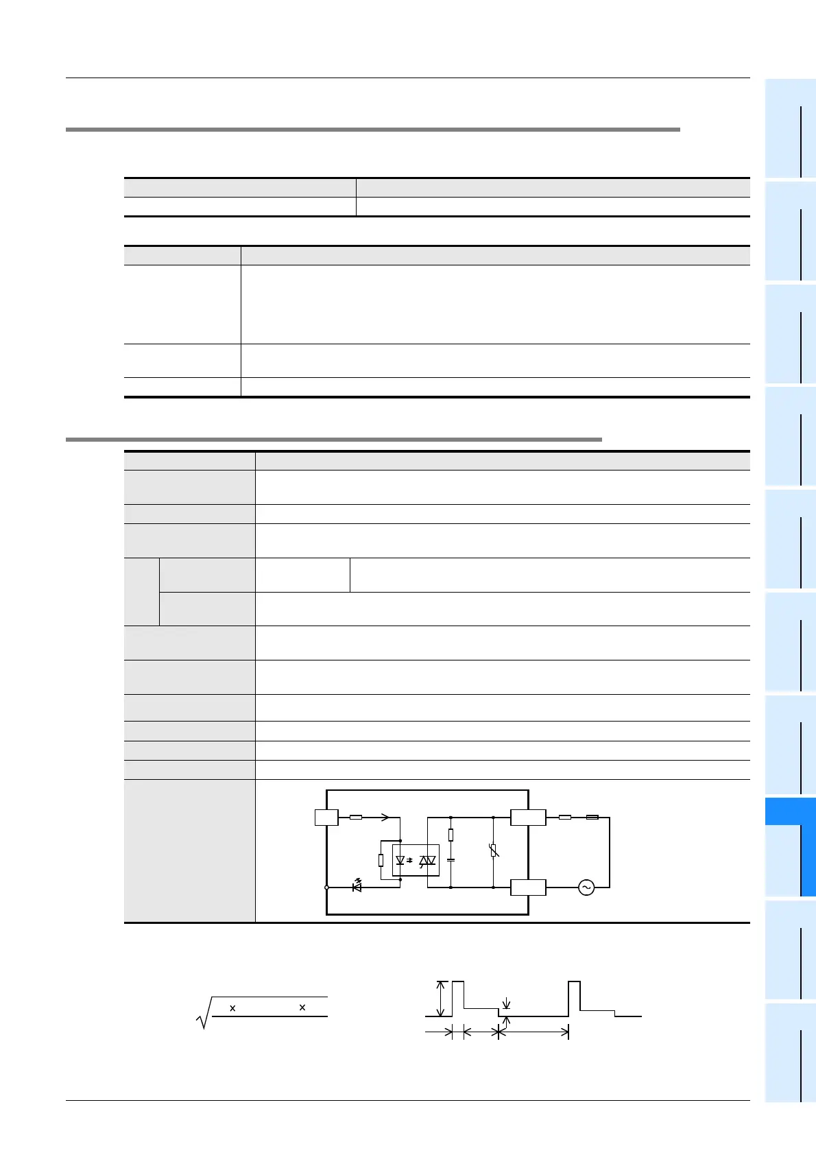
Input/output circuitry
0.015
µ
F
3.3k
Ω
2.2k
Ω
CN1
Connector
side
Photo-
thyristor
LED
U
Fuse
24+
External wiring
24V DC
7mA
COMn
0 to 7
0.4A
0.7
sec
4A
10
sec
0.02
sec
0.02 + 0.7 + 10
4
2
0.02 + 0.4
2
0.7
= 0.2A
<Example>
 Loading...


