279
FX3UC Series Programmable Controllers
User’s Manual - Hardware Edition
9 CC-Link/LT Built-in master ability (Only FX3UC-32MT-LT)
9.8 Connection of Cables, Connectors and Terminating Resistors
1
Outline
2
External
Dimensions
3
Generic
Specifications
4
Power Supply
Specifications
5
Input
Specifications
6
Output
Specifications
7
Examples of
Wiring for
Various Uses
8
Terminal Block
9
CC-Link/LT
Master FX
3UC
(LT only)
10
Display module
FX
3UC
(LT only)
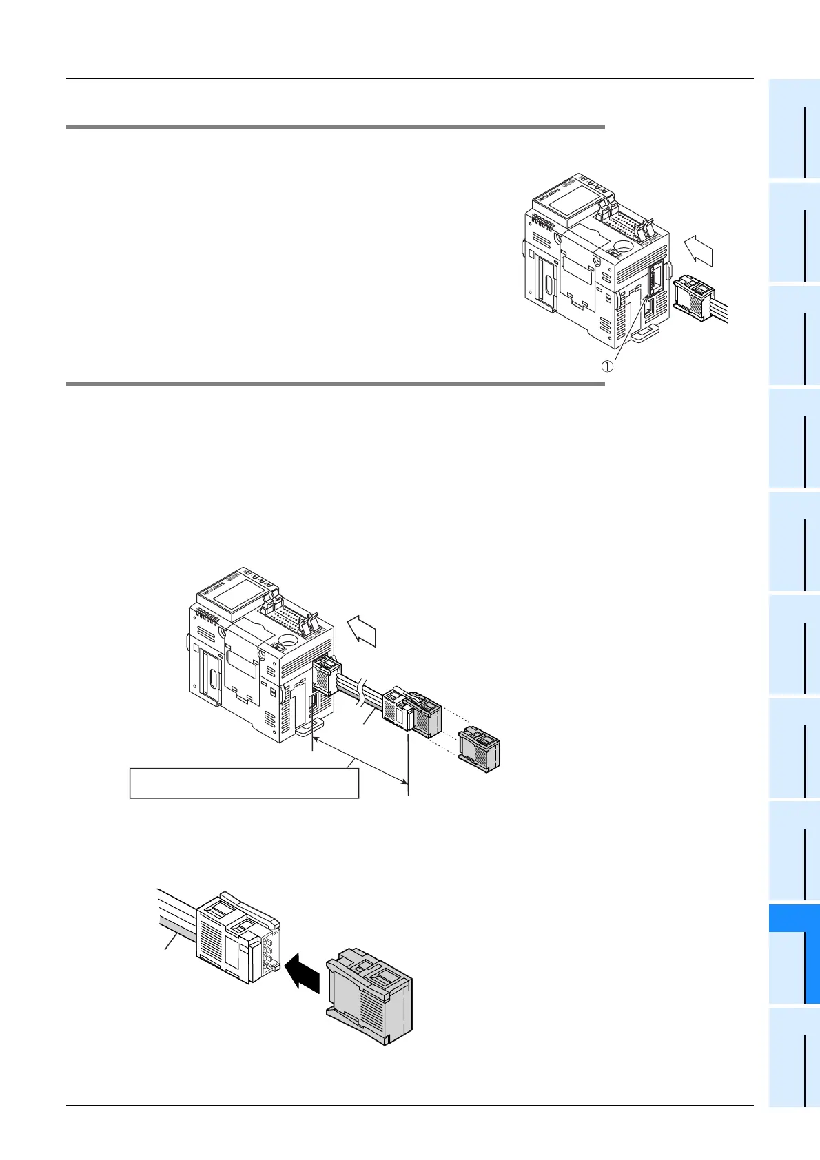
9.8.6 Connecting a connection cable to the CC-Link/LT interface connector
1. Connection procedure
Connect a connection cable to the CC-Link interface connector
(
c
in right figure).
9.8.7 How to attach a terminating resistor
This paragraph explains how to attach terminating resistors to either end of the CC-Link/LT system.
Attach a terminal resistor to the cable connector.
Caution:
The following example shows attachment to a CC-Link/LT dedicated cable.
Use the same method for a VCTF cable or high flexible cable.
→ For details on the terminating resistor attachment method for the built-in master when using
a VCTF or high flexible cable as the trunk line, refer to Subsection 9.5.3.
1. How to attach a terminating resistor on the FX3UC-32MT-LT built-in master side
Connect a terminating resistor in a position within 200mm (7.87") from the CC-Link/LT interface connector.
2. How to attach a terminating resistor on the trunk line side
The method to attach a terminating resistor on the opposite side of the FX3UC-32MT-LT built-in master is
shown below.
Connection
cable
Dedicated flat cable
Terminating resistor
FX
3UC-32MT-LT
Within 200mm (7.87") from the CC-Link/LT
interface connector
Orange
connector
Dedicated flat cable
Terminating resistor
Orange
connector
 Loading...


