81
FX3UC Series Programmable Controllers
User’s Manual - Hardware Edition
2 External Dimensions and Terminal Arrangement
2.1 External Dimensions (MASS/Installation/Accessories)
1
Outline
2
External
Dimensions
3
Generic
Specifications
4
Power Supply
Specifications
5
Input
Specifications
6
Output
Specifications
7
Examples of
Wiring for
Various Uses
8
Terminal Block
9
CC-Link/LT
Master FX
3UC
(LT only)
10
Display module
FX
3UC
(LT only)
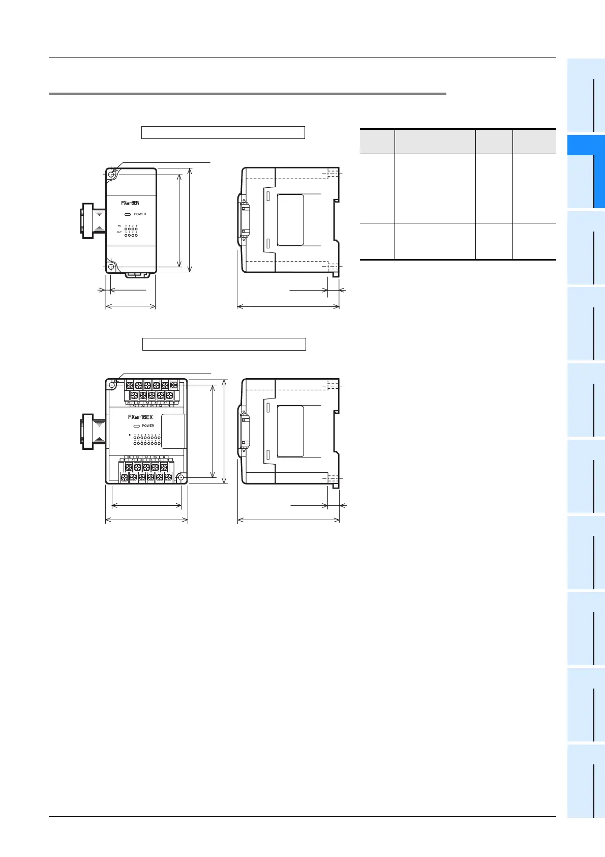
2.1.4 FX0N Series Input/output Extension Block
1. Terminal type
• Installation: DIN rail of 35 mm (1.38") in
width or screws
• Accessories: Label for indication of I/O
number,
• Terminal block: M3 screws
• The extension cable is already connected to
the extension block
Type Model name W(mm)
MASS
(Weight)
A
FX
0N-8ER
FX
0N-8EX
FX
0N-8EX-UA1/UL
FX
0N-8EYR
FX
0N-8EYT
FX
0N-8EYT-H
43
(1.70")
0.2
(0.44lbs)
B
FX
0N-16EX
FX
0N-16EYR
FX
0N-16EYT
70
(2.76")
0.3
(0.66lbs)
Unit:mm(inches)
Unit:mm(inches)
A type
B type
90(3.55")
80(3.15")
(mounting hole pitch)
90(3.55")
2-φ4.5 mounting holes
4(0.16")
W:43(1.70")
87(3.43")
9(0.36")
87(3.43")
9(0.36")
80(3.15")
(mounting hole pitch)
W:70(2.76")
60(2.37")
(mounting hole pitch)
2-φ4.5 mounting holes
 Loading...


