363
FX3UC Series Programmable Controllers
User’s Manual - Hardware Edition
10 Display Module (Only FX3UC-32MT-LT)
10.21 User Message Display Function
1
Outline
2
External
Dimensions
3
Generic
Specifications
4
Power Supply
Specifications
5
Input
Specifications
6
Output
Specifications
7
Examples of
Wiring for
Various Uses
8
Terminal Block
9
CC-Link/LT
Master FX
3UC
(LT only)
10
Display module
FX
3UC
(LT only)
10.21 User Message Display Function
The user message display function allows a user-prepared message to appear in place of the "Main unit I/O
operation display".
The [OK] button is then pressed to switch from the "user message screen" to the "menu screen".
If using fixed user messages, the messages (created in GX Developer’s "device memory" window) should be
saved individually at D + 9 to D + 40 of the file register (D), extended register (R), and extended file
register (ER).
→ Refer to Section 10.16 for system information setting.
→ Refer to Subsection 10.21.7 for character data input.
10.21.1 System information - user message display function
1. System signal 1
1) Displayable Characters & Codes
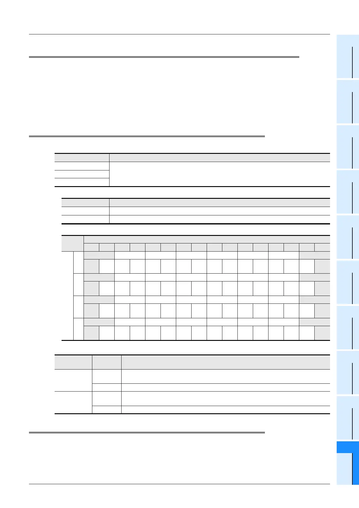
2) System information’s (system signal 1) D + 9 to D + 40 and display position
2. System signal 2
10.21.2 Shift JIS code arrangement precautions
To prevent garbled characters when a 2-byte character (shift JIS code) arrangement extends into the next
line, the system replaces those characters with 2 spaces.
[Ex] If a full-size character arrangement exists at D + 16 (higher order) + D + 17 (lower order), spaces
will display at those positions. Therefore, the use of full-size characters (shift JIS code) should be avoided at
the shaded areas shown in the above table.
System Information Description
D + 9
Device where the user message character string is saved.
~
D + 40
Character Type Code
Alphanumeric 20
H to 7DH, A1H to DFH ASCII code
Japanese Shift JIS Level 1-, 2
Row (horizontal character position)
[1] [2] [3] [4] [5] [6] [7] [8] [9] [10] [11] [12] [13] [14] [15] [16]
Line (vertical character position)
1
D + 9 D + 10 D + 11 D + 12 D + 13 D + 14 D + 15 D + 16
Lower
order
Higher
order
Lower
order
Higher
order
Lower
order
Higher
order
Lower
order
Higher
order
Lower
order
Higher
order
Lower
order
Higher
order
Lower
order
Higher
order
Lower
order
Higher
order
2
D + 17 D + 18 D + 19 D + 20 D + 21 D + 22 D + 23 D + 24
Lower
order
Higher
order
Lower
order
Higher
order
Lower
order
Higher
order
Lower
order
Higher
order
Lower
order
Higher
order
Lower
order
Higher
order
Lower
order
Higher
order
Lower
order
Higher
order
3
D + 25 D + 26 D + 27 D + 28 D + 29 D + 30 D + 31 D + 32
Lower
order
Higher
order
Lower
order
Higher
order
Lower
order
Higher
order
Lower
order
Higher
order
Lower
order
Higher
order
Lower
order
Higher
order
Lower
order
Higher
order
Lower
order
Higher
order
4
D + 33 D + 34 D + 35 D + 36 D + 37 D + 38 D + 39 D + 40
Lower
order
Higher
order
Lower
order
Higher
order
Lower
order
Higher
order
Lower
order
Higher
order
Lower
order
Higher
order
Lower
order
Higher
order
Lower
order
Higher
order
Lower
order
Higher
order
System
Information
Setting
Content
Screen Display
M+ 4
ON
User message display command.
This command is enabled only when the "Main unit I/O operation display" is displayed.
OFF Cancels the user message display, and displays the "Main unit I/O operation display".
M+ 6
ON
ON when the "user-registered device monitor screen"
or the "user message screen" is displayed.
OFF OFF when other screens are displayed.
 Loading...


