69
FX3UC Series Programmable Controllers
User’s Manual - Hardware Edition
1 Outline
1.14 Selection Calculation Example 3 for System Configuration
1
Outline
2
External
Dimensions
3
Generic
Specifications
4
Power Supply
Specifications
5
Input
Specifications
6
Output
Specifications
7
Examples of
Wiring for
Various Uses
8
Terminal Block
9
CC-Link/LT
Master FX
3UC
(LT only)
10
Display module
FX
3UC
(LT only)
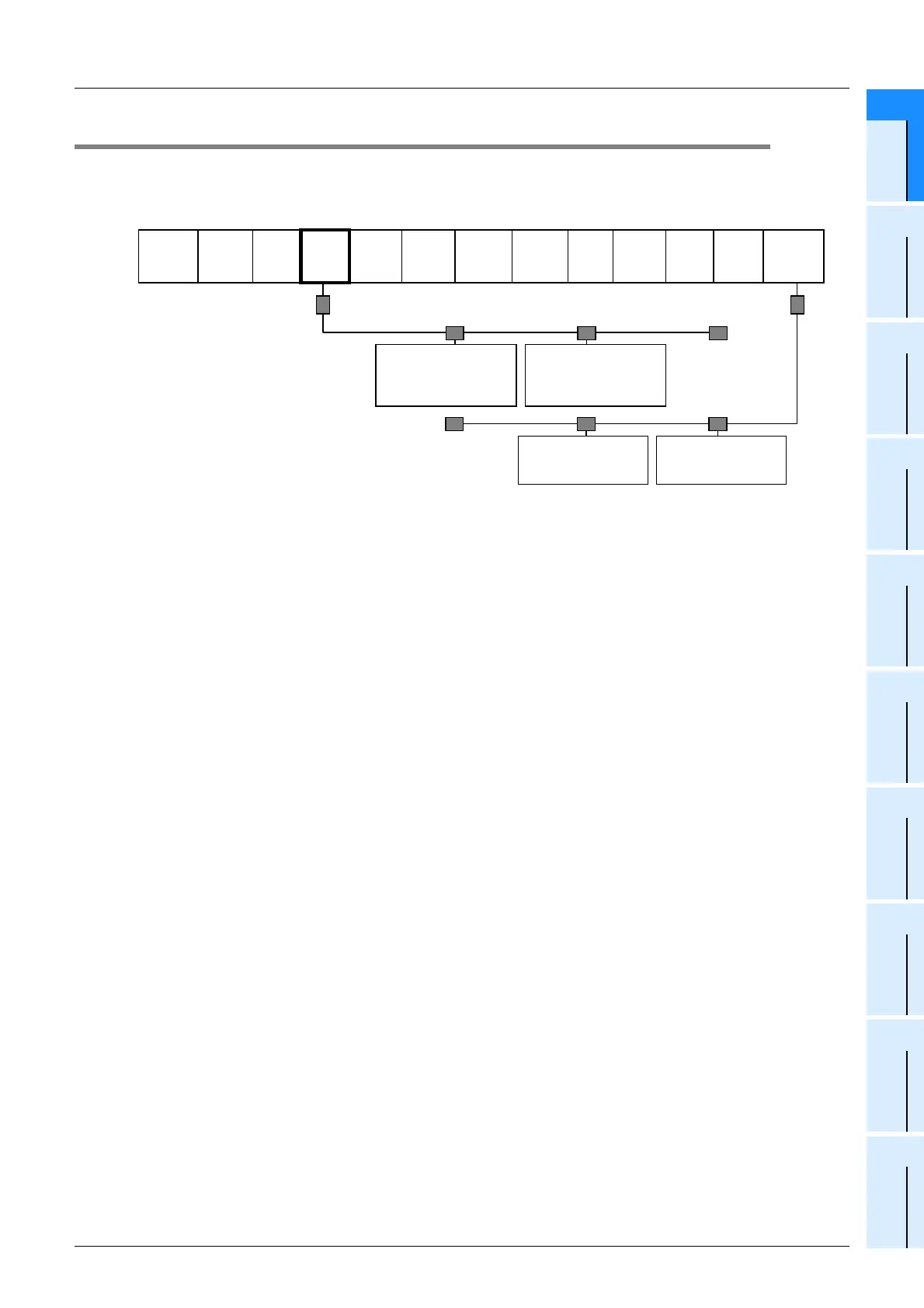
1.14 Selection Calculation Example 3 for System Configuration
When the main unit FX3UC-32MT-LT and CC-Link master are used.
For the calculation of power supply restrictions in the CC-Link/LT system, refer to Subsection 9.6.3.
1. Example system configuration
FX
3U
-
4AD-ADP
CC-Link/LT
CL1X4-D1B2
4 points, input units
(Station No.1, Number
of occupied stations 1)
CL1Y4-T1B2
4 points, output units
(Station No.2, Number
of occupied stations 1)
AJ65BTB1-16T
16 points input units
(Remote I/O station)
AJ65BTB1-16D
16 points input units
(Remote I/O station)
FX
3U
-
485-ADP
(-MB)
FX
3U
-
232-BD
FX
2NC
-
32EX
FX
2NC
-
32EYT
FX
2NC
-
16EYR-T
FX
2NC
-
16EYR-T
FX
2NC
-
4AD
FX
2NC
-
CNV-IF
FX
2N
-
10PG
FX
2N
-
2LC
FX
2N
-
16CCL-M
FX
3UC
-
32MT-
LT
Terminating resistor
Terminating
resistor
Terminating
resistor
Terminating
resistor
 Loading...


