311
FX3UC Series Programmable Controllers
User’s Manual - Hardware Edition
9 CC-Link/LT Built-in master ability (Only FX3UC-32MT-LT)
9.18 Details of buffer memory
1
Outline
2
External
Dimensions
3
Generic
Specifications
4
Power Supply
Specifications
5
Input
Specifications
6
Output
Specifications
7
Examples of
Wiring for
Various Uses
8
Terminal Block
9
CC-Link/LT
Master FX
3UC
(LT only)
10
Display module
FX
3UC
(LT only)
3. CONFIG mode (Cautions on use)
In CONFIG mode, if the detailed remote station information [BFM #32 (20h) to #95 (5Fh)] is edited, and if the
detailed remote station information is inconsistent with remote stations actually connected at the time of
power ON as a result of the editing, there will be a data link error.
(When BFM #32 (20h) to #95 (5Fh) is edited, the station numbers are checked.)
If the power is set to ON while all remote stations are unconnected or if remote stations are disconnected
after the power was set to ON, data link error is not detected, as long as the detailed remote station
information is not edited.
→ For details on the specification of a reserved station, refer to Section 9.12.
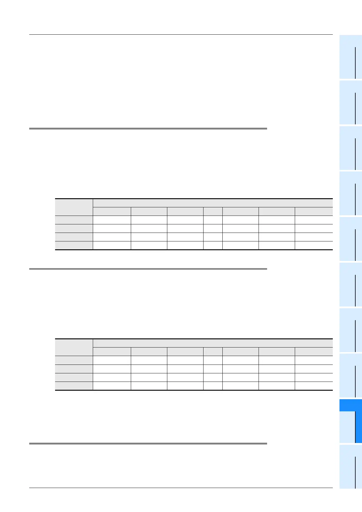
9.18.3 Remote I/O error information [BFM #8 (8h) to #11 (Bh)]
The remote I/O error occurrence status is stored here. (Bits for stations with I/O error are ON.)
For the type of error, refer to the instruction manual of each remote station.
1. Detailed description
The station number of each remote station is assigned to each bit of the buffer memory [BFM #8 (8h) to #11
(Bh)]. The absence/presence of remote I/O errors are indicated by the 0 (OFF)/1 (ON) status of each bit.
0 (OFF): Remote I/O error is absent
1 (ON): Remote I/O error is present
Initial value: 0 (OFF)
9.18.4 Reserved station information [BFM #16 (10h) to #19 (13h)]
Station numbers specified as reserved stations are stored here. (Bits for reserved stations are ON.)
1. Detailed description
The station number of each remote station is assigned to each bit of the buffer memory [BFM #16 (10h) to
#19 (13h)]. Whether or not a station is specified as reserved is indicated by the 0 (OFF)/1 (ON) status of each
bit.
0 (OFF): The station is not specified as a reserved one.
1 (ON): The station is specified as a reserved one.
Initial value: 0 (OFF)
2. Specify reserved stations
Specify reserved stations by editing the detailed remote station information [BFM #32 (20h) to 95 (5Fh)] in
CONFIG mode.
→ For details specification of reserved station, refer to Section 9.12.
9.18.5 Number of required input blocks [BFM #20 (14h)]
The number of input blocks (8 points/block) required to assign the I/O numbers of remote stations is stored
here.
Buffer
memory No.
Bit
b15 b14 b13 ••• b2 b1 b0
BFM #8 (0h) Station No.16 Station No.15 Station No.14 ••• Station No.3 Station No.2 Station No.1
BFM #9 (1h) Station No.32 Station No.31 Station No.30 ••• Station No.19 Station No.18 Station No.17
BFM #10 (2h) Station No.48 Station No.47 Station No.46 ••• Station No.35 Station No.34 Station No.33
BFM #11 (3h) Station No.64 Station No.63 Station No.62 ••• Station No.51 Station No.50 Station No.49
Buffer
memory No.
Bit
b15 b14 b13 ••• b2 b1 b0
BFM #16 (0h) Station No.16 Station No.15 Station No.14 ••• Station No.3 Station No.2 Station No.1
BFM #17 (1h) Station No.32 Station No.31 Station No.30 ••• Station No.19 Station No.18 Station No.17
BFM #18 (2h) Station No.48 Station No.47 Station No.46 ••• Station No.35 Station No.34 Station No.33
BFM #19 (3h) Station No.64 Station No.63 Station No.62 ••• Station No.51 Station No.50 Station No.49
 Loading...


