112
FX3UC Series Programmable Controllers
User’s Manual - Hardware Edition
3 Generic Specifications/Installation Work
3.4 Connection between main unit and extension equipment
3.4.5 Connecting method D (Connection of FX3UC-1PS-5V/FX2NC-CNV-IF to right side)
This subsection explains the procedures for connecting the extension cable to the extension power supply
unit FX
3UC-1PS-5V or the connector conversion interface FX2NC-CNV-IF.
1. Connection procedure
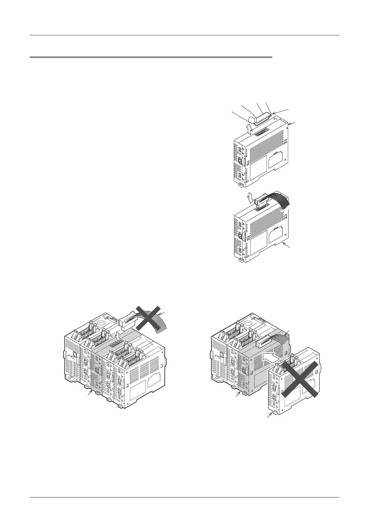
1) The connector cover (A) of the FX3UC-1PS-5V is removed as shown in the figure to the right.
The FX
2NC-CNV-IF does not have a connector cover.
2) Connect the extension cable as shown to the right.
2. Caution on the FX3UC-1PS-5V
Only one connector can be used to attach extra equipment to the FX3UC-1PS-5V.
Connector
cover (A)
FX
3UC-1PS-5V
FX
3UC-1PS-5V o
FX2NC-CNV-IF
extension cable
Downstream
When the FX2NC/FX3UC extension connector (on the
right side) of the FX
3UC-1PS-5V is being used
When the FX
2NC/FX3UC extension connector (on the
right side) of the FX
3UC-1PS-5V is being used, the
FX
0N/FX2N/FX3U extension block connector on the
top is not available.
When the FX
0N/FX2N/FX3U extension block connector
(on the top) of the FX
3UC-1PS-5V is being used, the
FX
2NC/FX3UC extension connector on the right side is
not available.
FX
2NC/FX3UC extension block
(FX
2NC/FX3UC special function block,
FX
2NC-CNV-IF, FX3UC-1PS-5V)
When the FX
0N/FX2N/FX3U extension block connector
(on the top) of the FX
3UC-1PS-5V is being used
Extension
cable
Extension
cable
FX
3UC-1PS-5V
FX
3UC-1PS-5V
 Loading...


