247
FX3UC Series Programmable Controllers
User’s Manual - Hardware Edition
8 Terminal Block Specifications and External Wiring
8.14 FX-16EYS-ES-TB/UL
1
Outline
2
External
Dimensions
3
Generic
Specifications
4
Power Supply
Specifications
5
Input
Specifications
6
Output
Specifications
7
Examples of
Wiring for
Various Uses
8
Terminal Block
9
CC-Link/LT
Master FX
3UC
(LT only)
10
Display module
FX
3UC
(LT only)
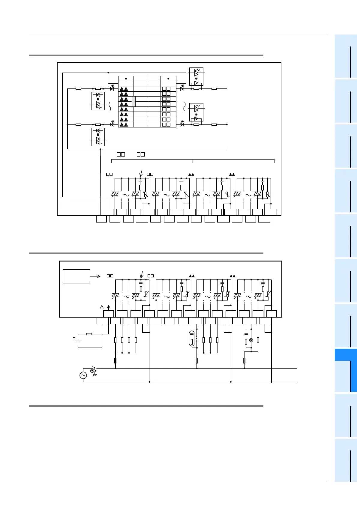
8.14.2 Internal circuit
8.14.3 Example of output external wiring
8.14.4 External wiring precautions
The caution on external wiring is the same as FX-16EYS-TB. Refer to Subsection 8.13.4.
Surge absorbers are connected to each output
0 to 7 Lower numbers
0 to
7 Higher numbers
3.3k
Ω
3.3k
Ω
3.3k
Ω
Photo-
thyristor
Photo-
thyristor
Photo-
thyristor
Photo-
thyristor
3.3k
Ω
1 3
4
5
60 2
7 1 3
0 2 4
5
6
724+
24-
COM1
COM1
COM2
COM2
COM3
COM3
COM4
COM4
(20)
+V0
6
7
5
4
3
2
1
0
+V0
6
7
5
4
3
2
1
0
(10)
(19) (9)
(18) (8)
(17) (7)
(6)
(5)
(4)
(3)
(2)
(1)
(16)
(15)
(14)
(13)
(12)
(11)
0123 4567 0123 4567
U
U
U
U
**
*. "+V1" or "+V2" in accordance with connected connector
1 3
4
5
60 2
7 1 3
0 2 4
5
6
724+
24-
COM1
COM1
COM2
COM2
COM3
COM3
COM4
COM4
0123 4567 0123 4567
U
U U U
PLC output
No.
Photo-coupler
power supply
24V
DC
Surge absorbers are connected to each output
Fuse Fuse Fuse
Load
 Loading...


