33
FX3UC Series Programmable Controllers
User’s Manual - Hardware Edition
1 Outline
1.3 Interpretation of Model Names (Main Units, I/O Extension Blocks)
1
Outline
2
External
Dimensions
3
Generic
Specifications
4
Power Supply
Specifications
5
Input
Specifications
6
Output
Specifications
7
Examples of
Wiring for
Various Uses
8
Terminal Block
9
CC-Link/LT
Master FX
3UC
(LT only)
10
Display module
FX
3UC
(LT only)
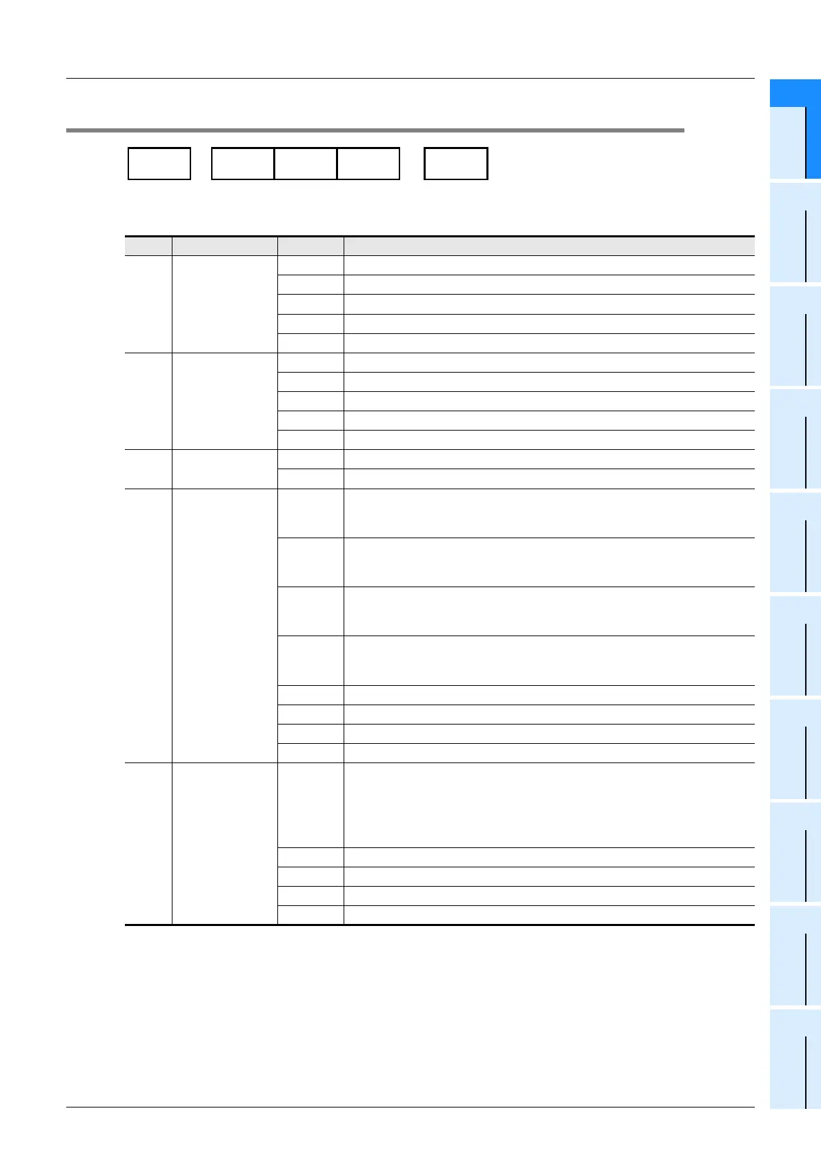
1.3 Interpretation of Model Names (Main Units, I/O Extension Blocks)
Classification Symbol Description
A Series name
FX
3UC FX3UC Series
FX
2NC FX2NC Series
FX
2N FX2N Series
FX
0N FX0N Series
FX FX Series
B
Total number of
I/O points
8 8 Points
16 16 Points
32 32 Points
64 64 Points
96 96 Points
C Classification 1
M Main units
E Input/Output extension blocks
D Input/output type
R
Input/output mixed
Input : 24V DC (Sink)
Output : Relay
T
T/D
Input/output mixed
Input : 24V DC (Sink)
Output : Transistor (Sink)
T/DSS
Input/output mixed
Input : 24V DC (Sink / Source)
Output : Transistor (Source)
X
Input dedicated
Classification 2 "None" : 24V DC Input
Classification 2 "UA1/UL" : 100V AC Input
XL Dedicated 5V DC Input
YR Dedicated relay output
YT Dedicated transistor output
YS Dedicated triac output
E Classification 2
Non
symbol
I/O connecting type
•FX
3UC Series : Connector
•FX
2NC Series : Connector
•FX
2N Series : Terminal block
•FX
0N Series : Terminal block
LT CC-Link/LT built-in master
UA1/UL 100V AC input type
C I/O connecting type : Connector
T I/O connecting type : Terminal block
Series
name
Total number
of I/O points
Classifi
cation1
Input/
output
type
Classifi
cation2
A-
-
B C D E
 Loading...


