113
FX3UC Series Programmable Controllers
User’s Manual - Hardware Edition
3 Generic Specifications/Installation Work
3.5 Expansion Board Connecting (Only FX3UC-32MT-LT)
1
Outline
2
External
Dimensions
3
Generic
Specifications
4
Power Supply
Specifications
5
Input
Specifications
6
Output
Specifications
7
Examples of
Wiring for
Various Uses
8
Terminal Block
9
CC-Link/LT
Master FX
3UC
-LT only
10
Display module
FX
3UC
-LT only
1
Outline
2
External
Dimensions
3
Generic
Specifications
4
Power Supply
Specifications
5
Input
Specifications
6
Output
Specifications
7
Examples of
Wiring for
Various Uses
8
Terminal Block
9
CC-Link/LT
Master FX
3UC
(LT only)
10
Display module
FX
3UC
(LT only)
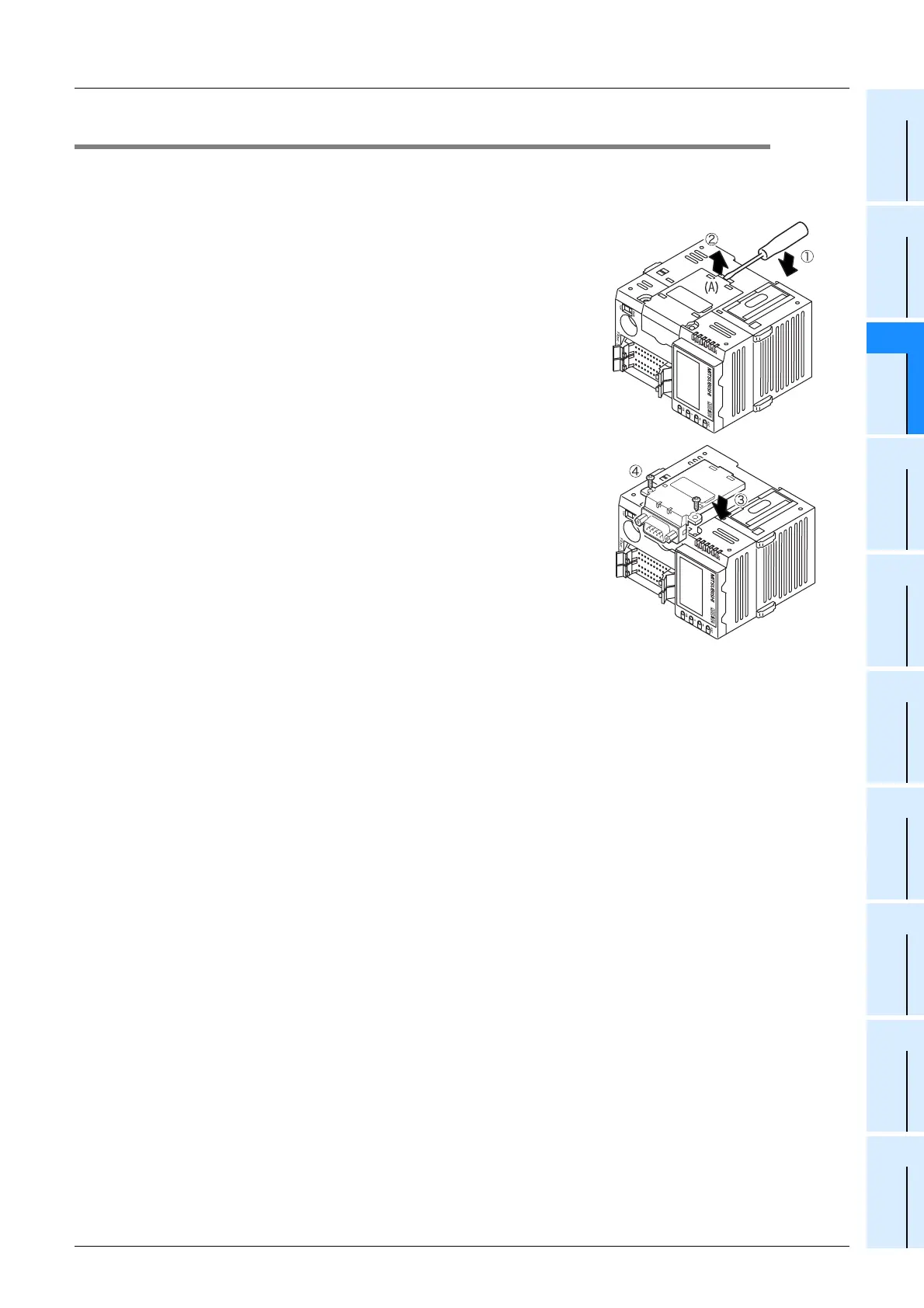
3.5 Expansion Board Connecting (Only FX3UC-32MT-LT)
The FX3UC-MT/D and FX3UC-MT/DSS do not support expansion boards.
1. Connection procedure
1) Disconnect all the cables connected to the PLC.
2) Demount the PLC from the DIN rail.
→ For the removal method, refer to Section 3.3.
3) Using a flat head screwdriver as shown in the figure on the
right, lift the dummy expansion board cover (fig. (A)) making
sure not to damage the circuit board or electronic parts. (fig.
c
)
4) Remove the expansion board dummy cover. (fig.
d
)
5)
Make sure the expansion board is in parallel with the main
unit and attach it to the expansion board connector. (fig.
e
)
6) Fix the expansion board to the main unit using the provided
M3 tapping screws. (fig.
f
)
Tighten to a torque of 0.3 to 0.6 N
•
m
 Loading...


