303
FX3UC Series Programmable Controllers
User’s Manual - Hardware Edition
9 CC-Link/LT Built-in master ability (Only FX3UC-32MT-LT)
9.15 Practical Program Examples
1
Outline
2
External
Dimensions
3
Generic
Specifications
4
Power Supply
Specifications
5
Input
Specifications
6
Output
Specifications
7
Examples of
Wiring for
Various Uses
8
Terminal Block
9
CC-Link/LT
Master FX
3UC
(LT only)
10
Display module
FX
3UC
(LT only)
9.15 Practical Program Examples
This section explains practical programs using the CC-Link/LT function.
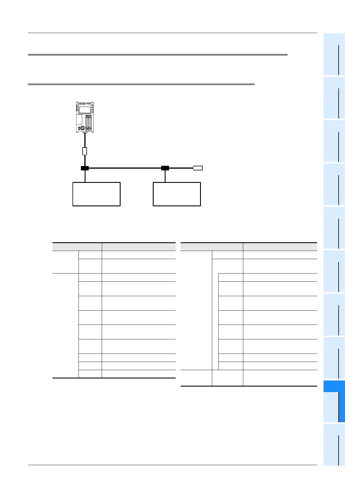
9.15.1 Practical Example 1 (Pattern 0)
1. System configuration examples
2. Device assignment
In this example, devices in the PLC are used as follows.
Device Description Device Description
Input (X)
X001 Data link stop instruction signal
Auxiliary
relay (M)
M0 For controlling the master
X002
Data link restart instruction
signal
M10 to M25
For reading the detailed error
information
Output (Y)
Y000 CC-Link/LT error has occurred M10 Data link error occurrence
Y001 Data link error occurrence M11
All-station data link error
occurrence
Y002
All-station data link error
occurrence
M12 Remote I/O error occurrence
Y003 Remote I/O error occurrence M13
Out-of-control-range error
occurrence
Y004
Out-of-control-range station
error occurrence
M14
Transmission speed setting
error occurrence
Y005
Transmission speed setting
error occurrence
M17 EEPROM error occurrence
Y010 EEPROM error occurrence M18 DIP switch changed
Y011 DIP switch changed M25 Hardware error occurrence
Y012 Hardware error occurrence
Data regis-
ter (D)
D10
Reads the error station
information
X020 to X023
Y020 to Y023
Terminating
resistor
Remote station
(station No. 2)
CL1XY8-DR1B2
Remote station
(station No.1)
CL1XY8-DR1B2
X024 to X027
Y024 to Y027
Terminating
resistor
Y000 to Y017
X000 to X017
FX
3UC
-32MT-LT
(Built-in master)
 Loading...


