261
FX3UC Series Programmable Controllers
User’s Manual - Hardware Edition
9 CC-Link/LT Built-in master ability (Only FX3UC-32MT-LT)
9.6 Selection of the power supply for CC-Link/LT
1
Outline
2
External
Dimensions
3
Generic
Specifications
4
Power Supply
Specifications
5
Input
Specifications
6
Output
Specifications
7
Examples of
Wiring for
Various Uses
8
Terminal Block
9
CC-Link/LT
Master FX
3UC
(LT only)
10
Display module
FX
3UC
(LT only)
9.6 Selection of the power supply for CC-Link/LT
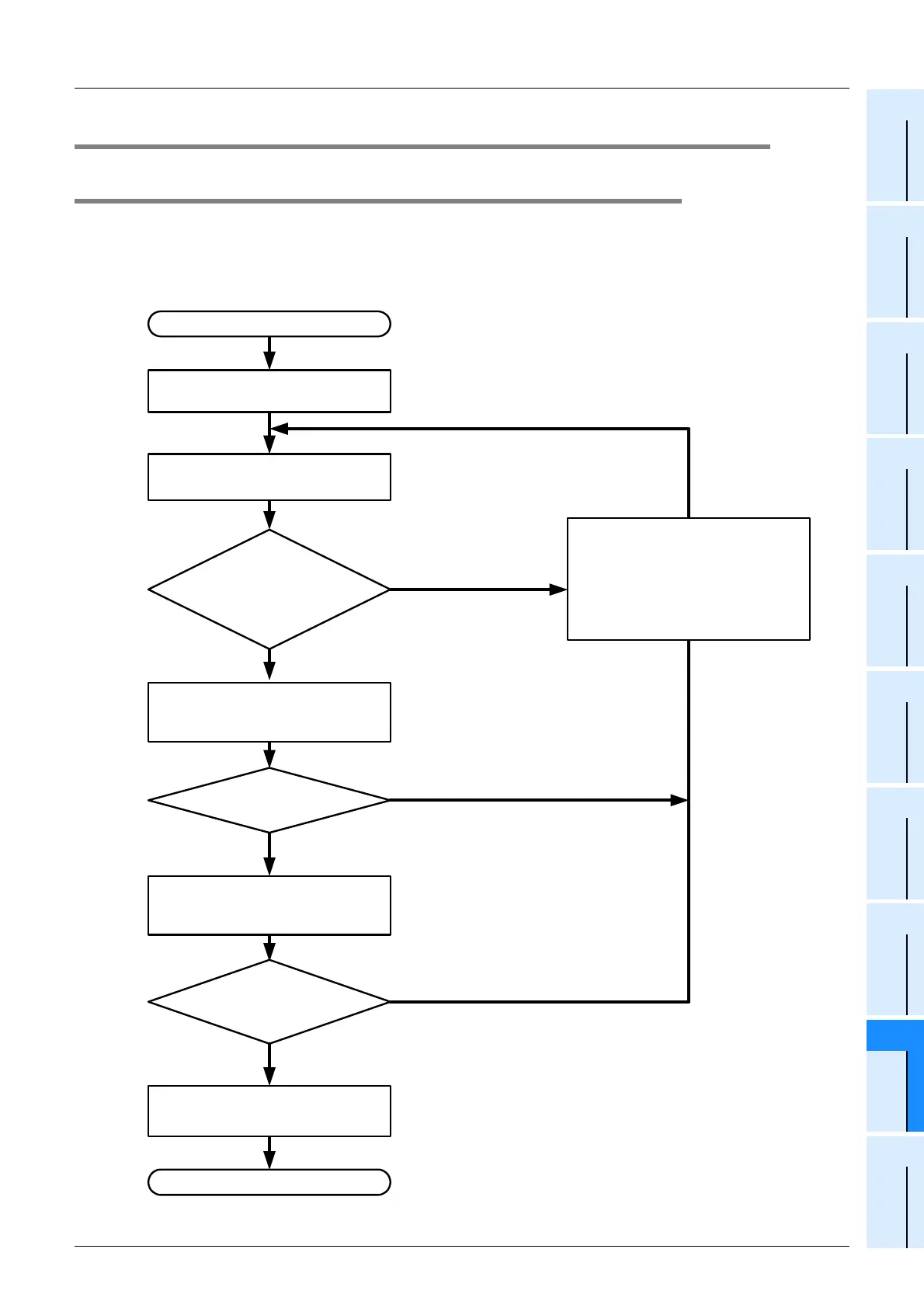
9.6.1 System power calculation procedure
Calculate the system power using the following procedure.
When the power supply adapter or dedicated power supply is required, refer to the appropriate manual for the
"current consumption" and "voltage drop" of the remote I/O stations connected to the power supply adapter/
dedicated power supply and later positions.
Calculation procedure
Calculate current consumption.
Refer to 9.6.3-1
Check simplified graph or calculate
voltage drop.
Refer to 9.6.3-2
Completed
YES
YES
NO
Design remote I/O station connection
configuration and wiring length design.
Examine the system using the power
supply adapter or dedicated power
supply.
Refer to Subsection 9.6.2.
For the power supply adapter or
dedicated power supply, refer to each
manual.
Start
Minimum operating voltage
(20.4 V) for each module shall be
assured.
Power supply voltage
- Voltage drop
≥
20.4V
NO
YES
Select general-purpose power supply.
Refer to 9.6.3-3
Check the built-in power supply again.
Is voltage drop
≤
3.6 V
NO
Total current
consumption of remote I/O
stations that receive power
from built-in power
supply
≤
0.35 A
 Loading...


