251
FX3UC Series Programmable Controllers
User’s Manual - Hardware Edition
9 CC-Link/LT Built-in master ability (Only FX3UC-32MT-LT)
9.1 Outline
1
Outline
2
External
Dimensions
3
Generic
Specifications
4
Power Supply
Specifications
5
Input
Specifications
6
Output
Specifications
7
Examples of
Wiring for
Various Uses
8
Terminal Block
9
CC-Link/LT
Master FX
3UC
(LT only)
10
Display module
FX
3UC
(LT only)
9.1.2 Major Procedures until Operation
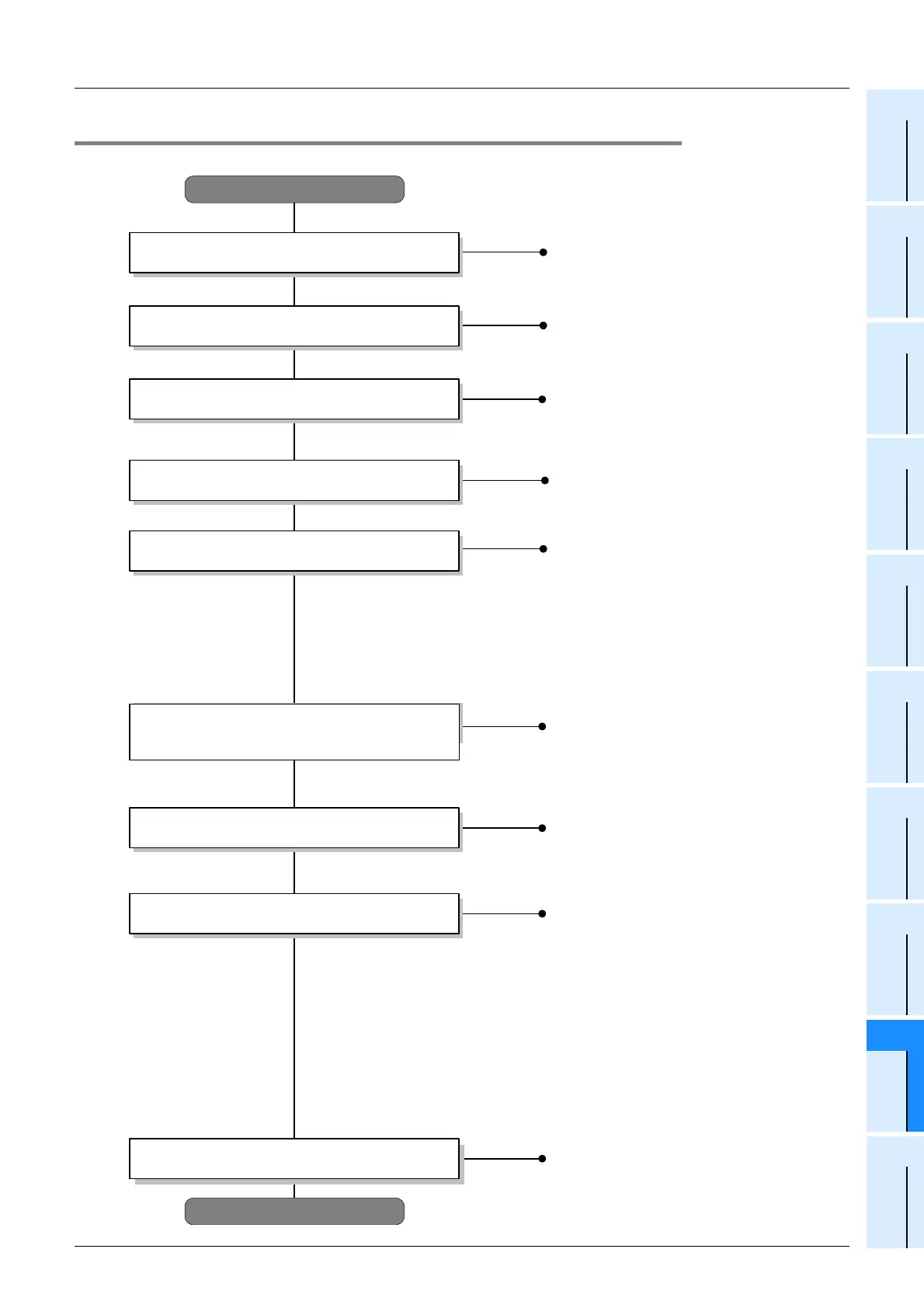
Start up the CC-Link/LT system using the following procedure.
Start
End
Connect the FX
3UC
-32MT-LT, remote I/O unit
and power adapter / dedicated power supply
with cables, and connect terminal resistors at
the ends of the trunk line.
Connection of cable wiring and
the terminating resistor
Refer to Section 9.8
Communication setting (DIP switches)
Refer to Section 9.9
Set the transmission speed, point mode,
station number, etc. of the FX
3UC
-32MT-LT
and remote modules using the DIP switches.
(Set the FX
3UC
-32MT-LT to the CONFIG
mode.)
- Confirm the installation status of the FX
3UC
-32MT-LT, remote modules and power
adapter / dedicated power supply.
- Confirm the supply voltage input to the FX
3UC
-32MT-LT.
- Confirm that the RUN/STOP switch for the FX
3UC
-32MT-LT is set to STOP.
- Confirm that the same station number is not used in two or more remote I/O stations or
remote device stations.
Check the following items before turning the power ON.
Check the following items before turning the
power ON
Specification of reserved station
(To be performed if necessary.)
Specify reserved stations for setting temporary
I/O numbers in advance and edit the detailed
remote station information here.
1.FX
3UC
-32MT-LT
- Data link is normal : L RUN (ON)
- Data link is abnormal : L ERR. ON/Flicker
- Setting is abnormal : Error occurrence (No LED display)
2.Remote I/O unit
- Confirm the remote station connection information using the buffer memory
[BFM #0 (0h) to #3 (3h)] in the FX
3UC
-32MT-LT built-in master.
- Confirm device operation using peripheral equipment for the PLC
(with regard to monitoring and forcing inputs + outputs ON and OFF).
Operation start and operation status check
Confirming the operation based upon LEDs
→
Refer to Section 9.18
→
Refer to Section 9.15
→
Refer to Section 12.5, 12.7
Refer to Chapter 3
Install the FX
3UC
-32MT-LT, remote modules
and power adapter / dedicated power supply to
the control panel and machine.
Installation
Automatic I/O numbers assignment
(Manual setting in "Edit detailed remote station
information")
Confirm the automatic I/O number assignment
operation and assignment rule.
Refer to Section 9.11, 9.13
I/Os can be assigned in "Edit detailed remote
station information" when all remote stations are
not connected.
Refer to Section 9.3, 9.6
Select the system configuration and power
supply adapter/dedicated power supply.
Examination of System Configuration
Programming
- Write a control program to the
FX
3UC
-32MT-LT.
- Operate the system
Refer to Section 9.15
Refer to Section 9.12, 9.13
Refer to the following
 Loading...


