255
FX3UC Series Programmable Controllers
User’s Manual - Hardware Edition
9 CC-Link/LT Built-in master ability (Only FX3UC-32MT-LT)
9.3 System configuration [CC-Link/LT Built-in master ability]
1
Outline
2
External
Dimensions
3
Generic
Specifications
4
Power Supply
Specifications
5
Input
Specifications
6
Output
Specifications
7
Examples of
Wiring for
Various Uses
8
Terminal Block
9
CC-Link/LT
Master FX
3UC
(LT only)
10
Display module
FX
3UC
(LT only)
9.3 System configuration [CC-Link/LT Built-in master ability]
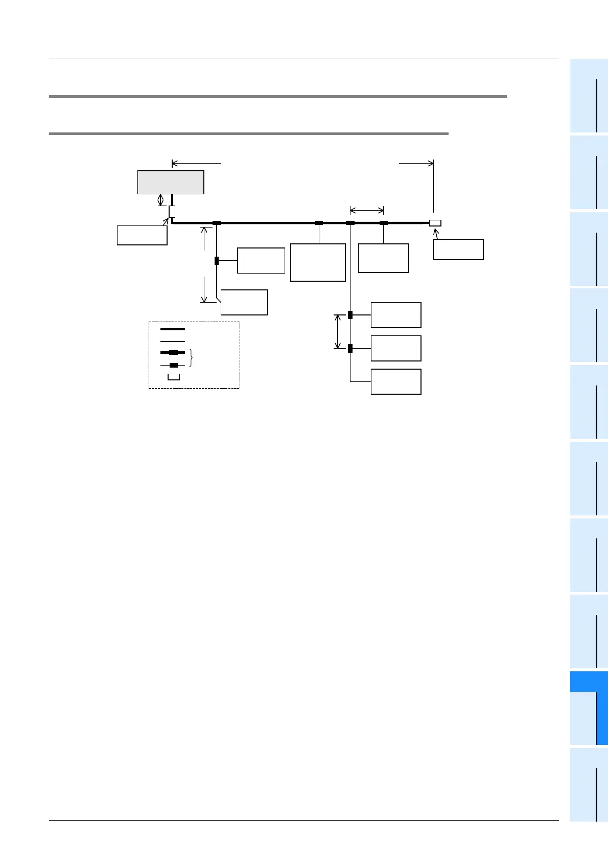
9.3.1 CC-Link/LT total configuration
This paragraph describes the system configuration and cautions for CC-Link/LT.
*1. The maximum drop line length and total drop line length include the branch length from the drop line.
1. Connection cable, Connector and Terminal block
Connect the CC-Link/LT built-in master, power supply adapter (dedicated power supply) and remote stations
through connectors for cable connection.
1) Connection cable
CC-Link/LT dedicated flat cables, VCTF cables and high flexible cables can be used together.
→ For details on combination and mixed use of cables, refer to Section 9.5.
2) Connecting the trunk line and drop line
The trunk line and drop line can be connected using connectors or terminal blocks.
Terminal blocks are available only when VCTF cables or high flexible cables are used.
→ For details on combination and mixed use of cables, refer to Section 9.5.
2. Connection of the CC-Link/LT built-in master
Make sure to install the Built-in master at the end of the trunk line.
3. Setting of the station number
The connection order of remote stations has no relevance to the station number.
Even if the station number of remote stations is not consecutive, no error will occur in the data link.
Use one station number only for one station.
→ For details, refer to "Subsection 9.9.2 Station number setting of the remote I/O units".
4. Terminating resistor
In the CC-Link/LT system, terminating resistors should be connected to both ends of the trunk line.
Connect the terminating resistor on the CC-Link/LT built-in master side to a position within 200mm (7.87")
from the Built-in master.
→ For details on how to attach terminating resistor, refer to Subsection 9.8.7.
5. Number of connectable units per built-in master
Up to 64 remote I/O stations and remote device stations can be connected in total (Up to 16 remote device
stations can be connected) only when the conditions described in "Network wiring specifications" is satisfied.
→ For details, refer to "Subsection 9.2.2 Network wiring specifications".
Terminating
resistor
T-branch
connection
T-branch
interval
Remote
I/O station
Remote
I/O station
Drop length
(including branch)
Remote
device
station
Remote
I/O station
Remote
I/O station
Remote
I/O station
Distance between
stations
Terminating
resistor
Trunk line
Drop line
Power
adapter or
dedicated
power supply
Trunk length (branch line length not included)
FX
3
UC
-32MT-LT
(Built-in master)
200mm (7.87")
or less
T-branch
Terminating
resistor
 Loading...


