238
FX3UC Series Programmable Controllers
User’s Manual - Hardware Edition
8 Terminal Block Specifications and External Wiring
8.11 FX-16EYT-ES-TB/UL
8.11 FX-16EYT-ES-TB/UL
Connect the FX-16EYT-ES-TB/UL to the output connector in the main unit or extension block shown in the
table below.
The applications shown below are not supported.
8.11.1 Specifications
*1. This response time does not include the response delay at the PLC.
Output connector
Connectable models FX
3UC-MT/DSS, FX2NC-EYT-DSS
Unsupported Applications
Pulse output
Pulse Y output (PLSY) instruction, acceleration/deceleration setup (PLSR) instruction, pulse width
modulation (PWM) instruction, DOG search zero return (DSZR) instruction, interruption positioning
(DVIT) instruction, batch data positioning mode (TBL) instruction, absolute current value read (ABS)
instruction, zero return (ZRN) instruction, variable speed pulse output (PLSV) instruction, drive to
increment (DRVI) instruction, drive to absolute (DRVA) instruction
Time division
input
Input matrix (MTR) instruction, hexadecimal input (HKY) instruction, digital switch (DSW) instruction,
arrow switch (ARWS) instruction
Time division
output
Seven segment with latch (SEGL) instruction, print (ASCII Code) (PR) instruction
Item FX-16EYT-ES-TB/UL
Connection form
Terminal block (M3.5 screw)
The connection with the PLC is the connector.
Output type/form Transistor/sink output
External power supply 5 to 30V DC
Max. load
Resistance
load
0.5A/1points
Make sure that the total load current of 4 resistance load points is
0.8A or less.
Inductive
load
12W/24V DC
Open-circuit leakage
current
0.1mA/30V DC
Response
time
OFF → ON
*1
0.2ms or less/24V DC
ON → OFF
*1
1.5ms or less/24V DC
Output element’s ON
voltage
1.5V
Circuit isolation Photocoupler isolation
Operation indicators LED lights when photo-thyristor power is supplied
Power consumption 2.7W (112mA 24V DC)
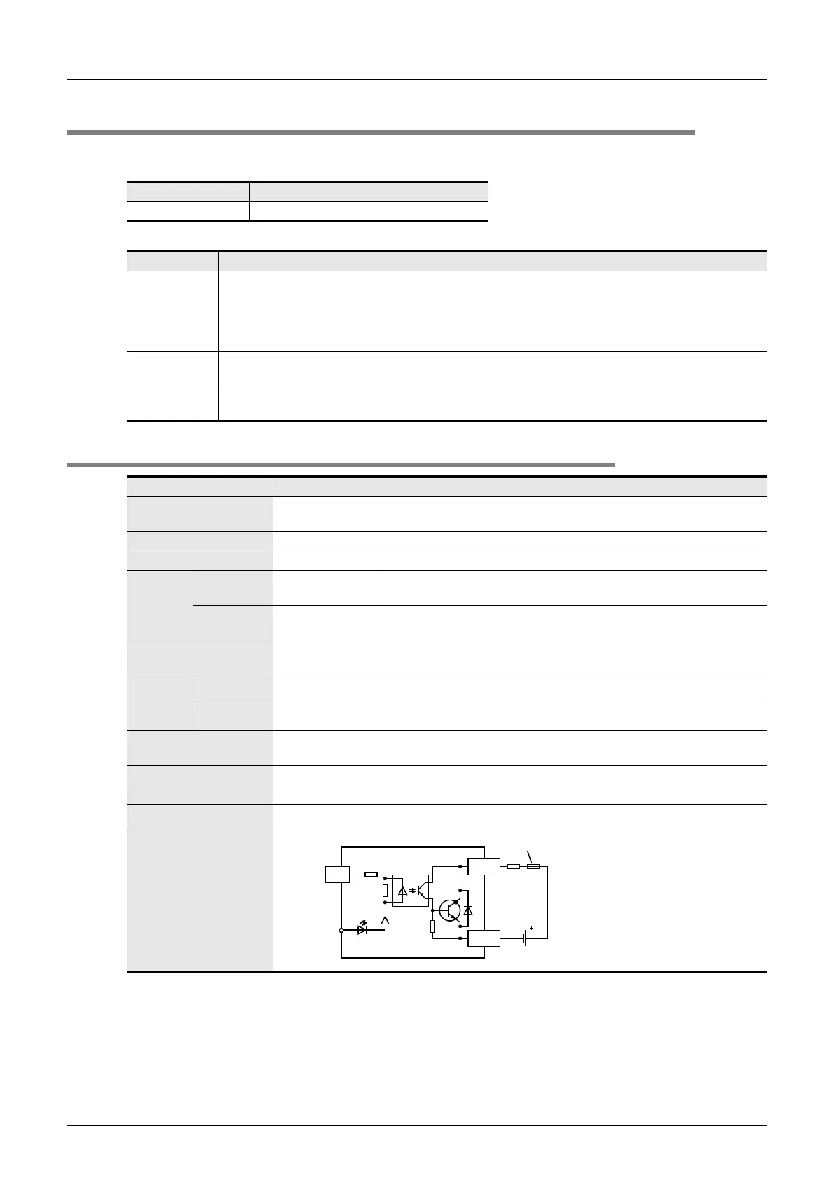
Input/output circuitry
24V DC
7mA
LED
Photo-
coupler
CN1
Connector
side
0 to 7
COMn
Fuse
24-
3.3k
Ω
5 to 30V
DC
External wiring
 Loading...


