RL78/G15 CHAPTER 4 PORT FUNCTIONS
R01UH0959EJ0110 Rev.1.10 Page 116 of 765
Mar 7, 2023
4.5 Register Settings When Using Alternate Function
4.5.1 Basic concept when using alternate function
In the beginning, for a pin also assigned to be used for analog input, use the port mode control registers 0, 2 (PMC0,
PMC2) to specify whether to use the pin for analog input or digital input/output.
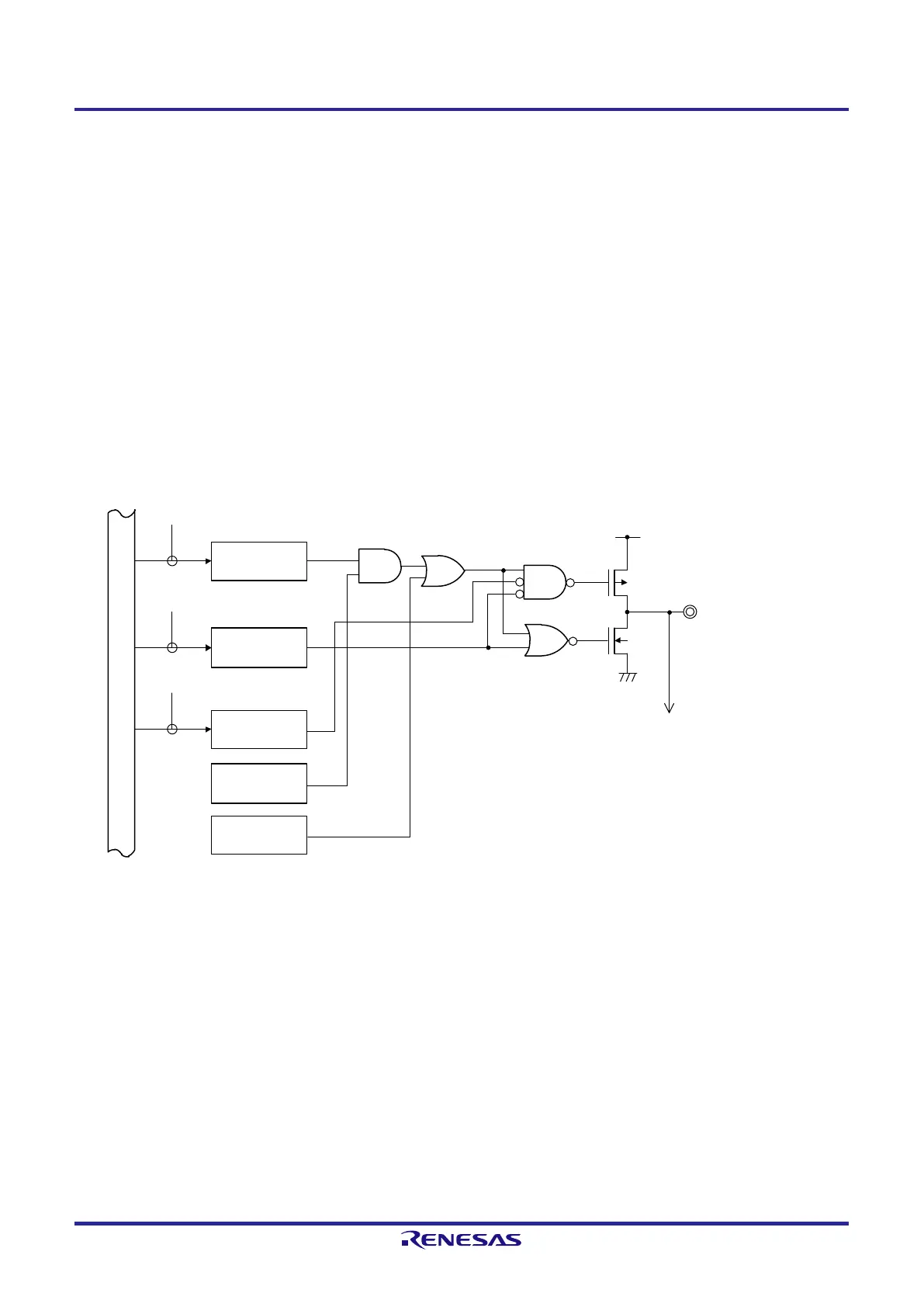
Figure 4-7 shows the basic configuration of an output circuit for pins used for digital input/output. The output of the
output latch for the port and the output of the alternate SAU function are input to an AND gate. The output of the AND
gate is input to an OR gate. The output of an alternate function other than SAU (TAU, clock/buzzer output, IICA, etc.) is
connected to the other input pin of the OR gate. When such kind of pins are used as the port function or an alternate
function, the unused alternate function must not hinder the output of the function to be used. An idea of basic settings for
this kind of case is shown in Table 4-6.
Figure 4-7. Basic Configuration of Output Circuit for Pins
Output latch
(Pmn)
POM register
(POMmn)
Alternate function
(SAU)
Alternate function
(other than SAU)
Pmn/Alternate function
To input circuit
WR
PM
WR
POM
V
DD
V
SS
P-ch
N-ch
Note 1
Note 3
PM register
(PMmn)
WR
PORT
Note 2
Internal bus
Note 1. When there is no POM register, this signal should be considered to be low level (0).
Note 2. When there is no alternate function, this signal should be considered to be high level (1).
Note 3. When there is no alternate function, this signal should be considered to be low level (0).
Remark m: Port number (m = 0, 2, 4, 12, 13); n: Bit number (n = 0 to 7)
 Loading...


